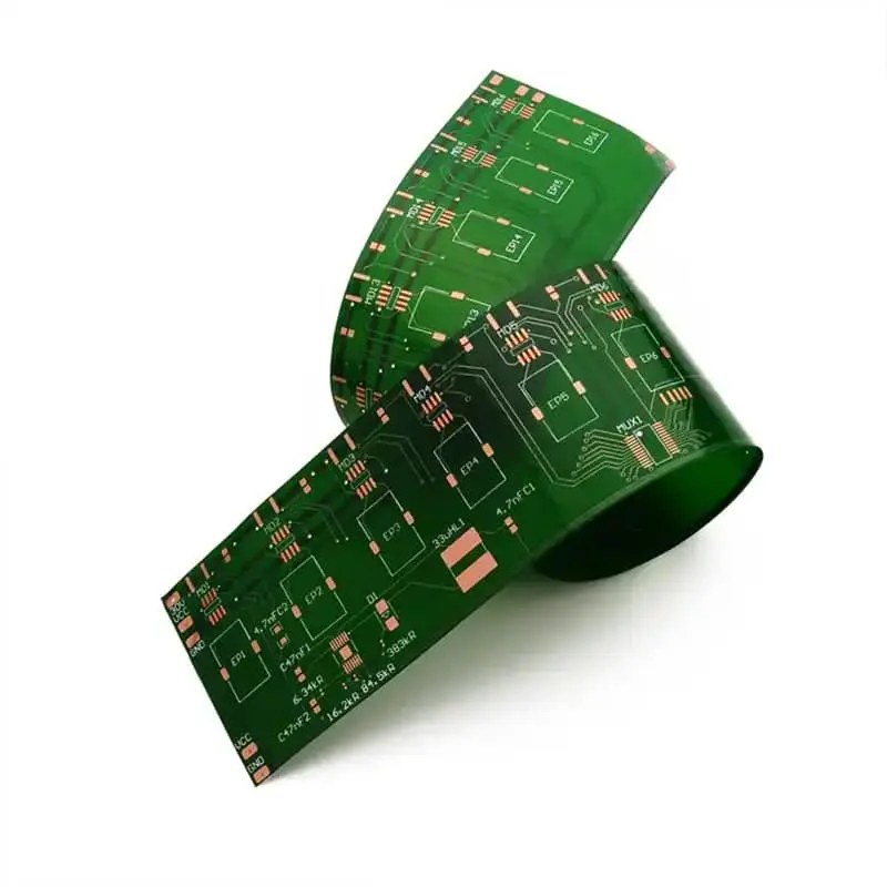
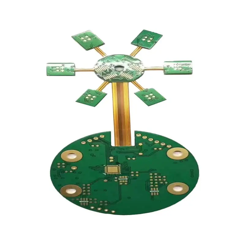
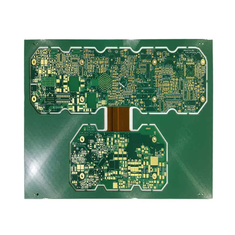
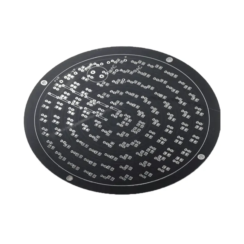
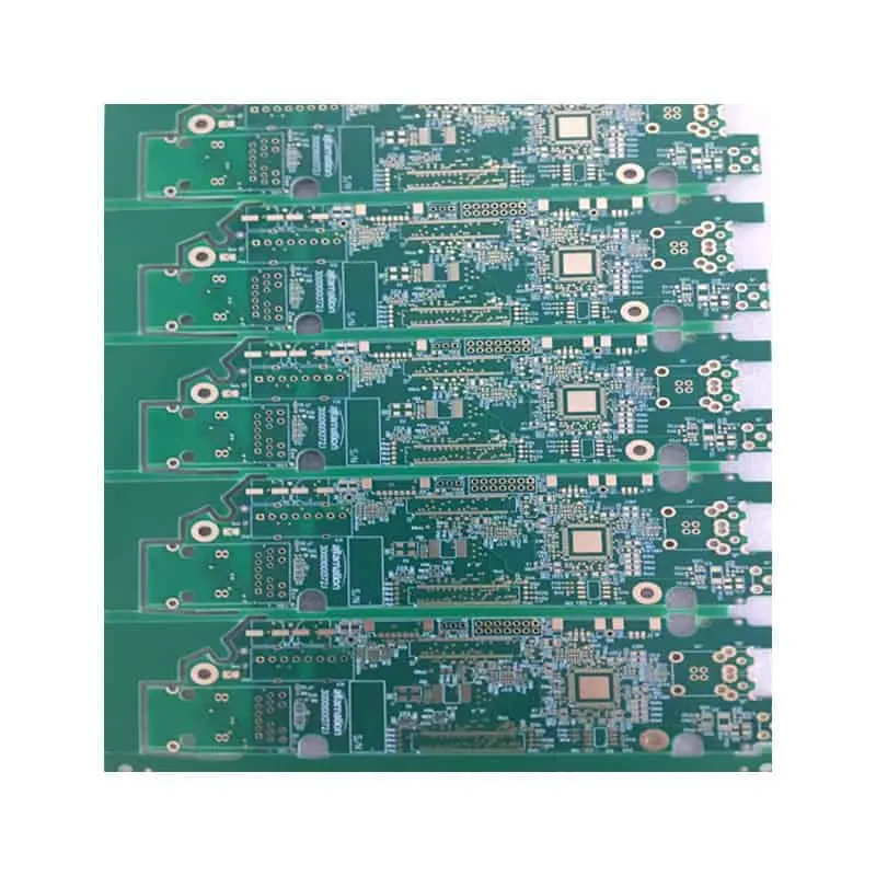
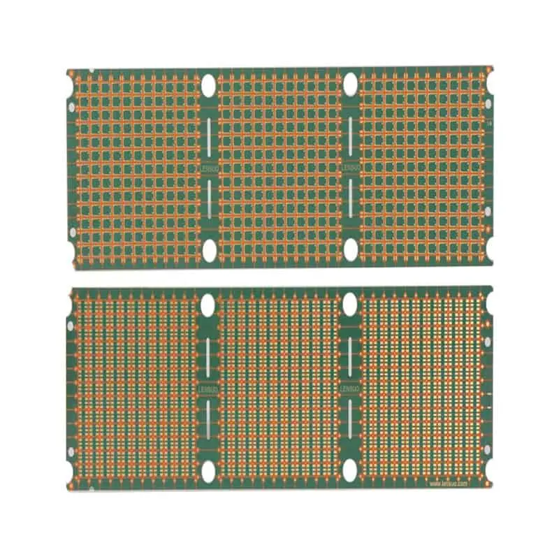
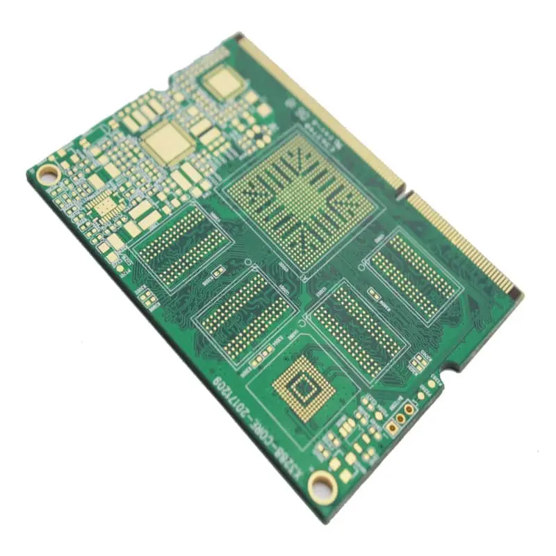
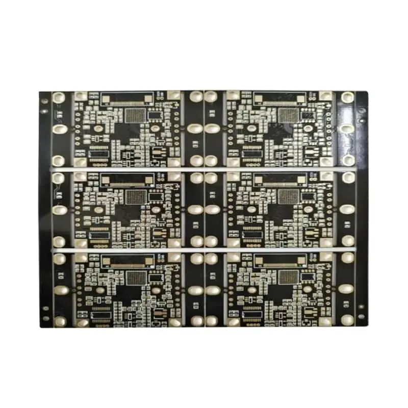
Rogers PCBs quality control and inspection are essential for high‑frequency builds, as Rogers high‑frequency PCBs serve critical RF, microwave, antenna, and mm‑wave applications where stable Dk/Df, precise impedance control, and consistent material performance directly determine end‑product reliability. Unlike commodity FR‑4 boards, Rogers laminates—including ceramic‑filled hydrocarbon and PTFE‑based grades—demand material‑specific quality workflows rather than generic PCB inspection checklists. For North‑American RF customers, full traceability, certified documentation, and repeatable test results are mandatory audit requirements. Below breaks down the complete QC workflow, from incoming laminate receipt through final order release.
Incoming Rogers Laminate Verification, Certificates, and Storage Controls
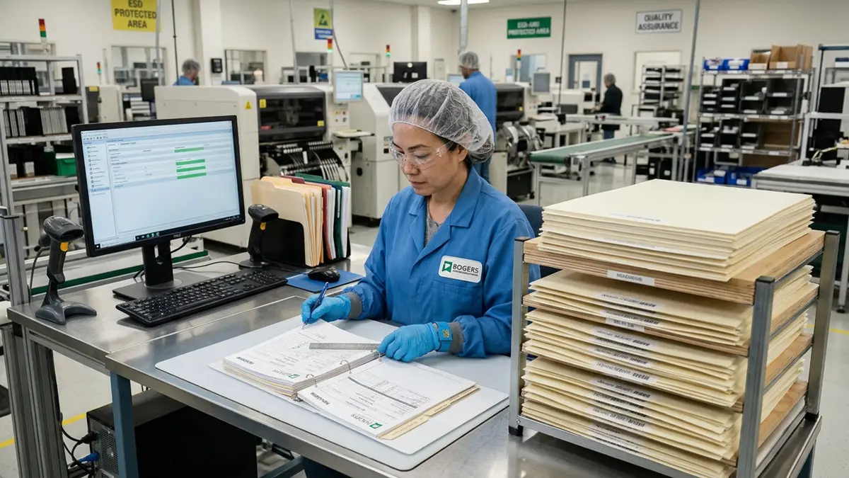
Rogers PCBs quality control and inspection: incoming Rogers laminate verification, certificate checking and proper material storage
Robust incoming material validation forms the first defensive gate for Rogers PCB quality. Many fabricators mistakenly reuse standard FR‑4 receiving workflows, creating hidden risks for high‑frequency builds. Upon material delivery, QA teams must cross‑check part numbers, manufacturing lot codes, and batch labels against customer purchase orders and stack‑up specifications. The mandatory verification checklist includes original supplier certificates of conformance (CoC), material datasheet alignment, nominal dielectric thickness tolerance, copper‑foil type, and published Dk/Df values at target operating frequenciesRogers Cor…. Every lot number must be logged into the manufacturing traceability system to enable full backward tracing if field issues emerge, a requirement heavily emphasized by US‑based RF buyers.
Special handling and storage rules apply especially for PTFE‑core Rogers laminates. Panels require flat horizontal storage inside original sealed packaging to avoid surface contamination, copper oxidation, and dimensional warpage. Storage environments maintain controlled ambient temperature between 18 °C‑30 °C and moderate humidity; direct contact with dust, moisture, or chemical vapors is prohibitedRogers Cor…. Operators must wear lint‑free gloves during panel handling to prevent surface residues that degrade high‑frequency signal performance. Material stock follows strict first‑in‑first‑out inventory rotation. Reject or quarantine any laminate showing physical scratches, dents, packaging damage, or certificate mismatches before allowing entry to production. Skipping these Rogers‑specific receiving and storage protocols often introduces impedance drift and yield loss that cannot be corrected in later fabrication stages.
In‑Process Inspection Checkpoints for Drilling, Plating, Lamination, AOI, and X‑Ray
Process‑stage inspection must account for Rogers materials’ narrow processing windows, which differ substantially from FR‑4 substrates. Direct copy‑and‑paste of FR‑4 inspection tables frequently leads to uncaught manufacturing defects for high‑frequency orders.
At drilling operations, inspectors monitor drill smear, PTFE burr formation, and hole‑wall roughness. Sampling frequency follows lot size; any visible PTFE smearing triggers process review, as residual smear impairs copper‑plating adhesion. Next, plating‑process audits measure plated‑copper thickness uniformity and copper peel strength against IPC‑6018 high‑frequency criteria. Lamination cycles require full profile validation: temperature, pressure, dwell‑time parameters for Rogers‑only or hybrid Rogers‑FR4 stack‑ups are logged for each press run to mitigate voiding and delamination risks.
Automated Optical Inspection (AOI) executes inner‑ and outer‑layer pattern checks to catch open circuits, shorts, trace‑width deviations, and copper nicks critical for controlled‑impedance traces. AOI alone cannot capture hidden inner‑layer misregistration or buried‑via anomalies, so periodic X‑ray sampling supplements visual checks for multi‑layer high‑frequency boards. When inspection fails any checkpoint, production pauses immediately for root‑cause analysis. Affected panels are segregated, and process parameters adjusted before production resumes. Each inspection result links back to the original raw‑material lot code, maintaining traceability across manufacturing operations.
Impedance and Electrical Performance Testing for Rogers High‑Frequency PCBs
Electrical‑performance validation differentiates competent Rogers PCB suppliers from general‑purpose PCB shops. Simply running continuity testing is insufficient for RF‑microwave customer requirements. Test‑coupon structures, co‑fabricated alongside production panels, replicate transmission‑line geometries defined in customer stack‑up documents. These coupons travel through identical fabrication steps as functional circuit boards to deliver representative measurement dataRogers Cor….
Before testing, measurement instruments complete formal calibration at the exact operating frequencies specified by the customer. Technicians measure target impedance values and extract practical Dk/Df performance derived from manufactured coupons rather than relying purely on laminate datasheet theoretical values. Signal‑integrity observations capture insertion‑loss trends relevant for mm‑wave and high‑speed RF designs.
For US customers, test‑result traceability is non‑negotiable. Every measurement record references the corresponding production lot number, panel ID, and test‑coupon location. When impedance or dielectric‑property results fall outside allowable tolerances, teams initiate formal non‑conformance workflows: isolate suspect units, review stack‑up execution, drilling, etching and lamination parameters, and determine whether boards qualify for rework, scrap, or conditional concession. Raw test datasets are retained and available for customer review upon request.
Coupon, Microsection, and Ionic Cleanliness Validation
Destructive laboratory testing validates hidden construction quality that non‑destructive inspections cannot expose. Representative coupons are harvested from production panels per defined sampling frequency, tied to manufacturing lots. Microsection analysis is performed to evaluate hole‑wall copper coverage, inter‑layer bonding quality, void percentage within dielectric and bonding interfaces, and registration of inner‑layer features. Acceptance thresholds align with IPC‑6018 specifications for high‑frequency hardware. Rogers PTFE‑containing materials require careful sample preparation during microsectioning to avoid smearing or material tearing that distorts defect assessment.
Ionic‑cleanliness testing assesses residual ionic contamination left from chemical fabrication processes. Surface ionic residues degrade high‑frequency performance, increase leakage current, and risk long‑term corrosion, particularly critical for antenna and outdoor RF hardware. Test acceptance limits are agreed with customers or referenced to applicable IPC standards. If cleanliness readings exceed thresholds, cleaning processes are reviewed and adjusted. All micro‑section images, measurement metrics, and ionic‑cleanliness numerical results are archived as part of the order‑quality package.
Final Inspection, Defect Classification, and Traceability Documentation
Final inspection and order release consolidate all earlier quality evidence before shipment. QC technicians perform dimensional verification against customer drawings, checking board outline tolerances, hole‑size accuracy, and milling quality. Visual inspection reviews outer‑layer copper features, solder‑mask integrity, silkscreen print quality, and surface‑finish uniformity. Every detected defect is classified per IPC‑A‑600 acceptability criteria, sorted into categories: acceptable, reworkable, non‑conforming scrap, or candidate for customer concession. Strict rules govern concession‑approval workflows; no high‑frequency electrical‑performance‑related defects receive unconditional pass status.
Full traceability documentation packages are assembled for each completed lot. Typical deliverables include incoming‑laminate certificates, in‑process inspection logs, impedance and Dk/Df test reports, micro‑section snapshots, ionic‑cleanliness records, UL/IPC compliance statements, and full batch genealogy mapping raw‑material lots through to finished‑board serial numbers. US‑based OEMs regularly request these documents for supplier audits. Only boards passing all visual, dimensional, electrical, and documentation checks receive formal release approval for packing and shipment.
Get Your Custom Rogers PCB Inspection Plan & Quotation
Quality assurance for Rogers‑series high‑frequency PCBs cannot rely on generic checklists. It demands a closed‑loop system spanning incoming‑material qualification, tailored in‑process monitoring, targeted high‑frequency electrical validation, laboratory destructive analysis, and complete traceable documentation.
If you are sourcing Rogers‑based RF or microwave PCBs, submit your stack‑up requirements, impedance specifications, project volume, and target application details. Our engineering team will prepare a project‑specific inspection scope and competitive quotation aligned with North‑American customer audit expectations.
Frequently Asked Questions
What are the key quality control steps in manufacturing Rogers PCBs, from incoming material to final release?
Core stages include incoming‑laminate verification and controlled storage, customized in‑process inspection for drilling, plating, lamination, AOI and X‑ray, impedance and high‑frequency electrical testing, coupon‑supported micro‑section plus ionic‑cleanliness validation, and final inspection with complete traceability documentation before shipment.
How should Rogers PTFE laminates be stored and handled to prevent moisture, contamination, and dimensional issues?
Store within factory‑sealed packaging under controlled temperature‑humidity conditions, use flat horizontal stacking, implement FIFO stock rotation, and require lint‑free gloves for all manual handling. Avoid dust, chemical fume exposure and mechanical panel bending.
Which in‑process inspection checkpoints matter most for high‑frequency Rogers boards?
Critical points cover drilling smear and burr inspection, plating thickness and adhesion testing, full lamination‑cycle logging, AOI pattern verification, plus X‑ray spot‑checking for inner‑layer mis‑registration and hidden via defects.
How do you verify impedance and Dk/Df performance on Rogers PCB test coupons?
Application‑specific test coupons are co‑produced with real production panels. Instruments are calibrated at customer‑specified frequencies; measured impedance and extracted Dk/Df data are logged with full lot traceability rather than using only theoretical datasheet values.
When are coupon microsections and ionic cleanliness tests required, and how are the results judged?
Coupons are sampled from production runs; microsections assess hole‑wall quality, bonding voids and inter‑layer alignment following IPC‑6018. Ionic‑cleanliness results compare against agreed‑upon contamination limits; out‑of‑spec results trigger cleaning‑process optimization.
What defects are most common in Rogers PCB manufacturing, and how should they be classified?
Frequent defects include PTFE drill smear, lamination voids, impedance deviation, trace‑width error, and surface ionic residues. Defects are classified per IPC‑A‑600 as acceptable, reworkable, scrap, or eligible for formal customer concession.
What traceability records and supplier certificates should accompany a Rogers PCB order?
Complete deliverables include laminate CoC certificates, in‑process inspection logs, impedance and Dk/Df test reports, micro‑section evidence, ionic‑cleanliness data, compliance statements, and batch‑traceability mapping linking finished boards back to original raw‑material lots.
About Author
David Chen LinkedIn Profile
David Chen is a Senior RF/PCB Process Engineer at Shenzhen Hongda Circuit Technology Co., Ltd., with over 12 years of experience in high-frequency PCB fabrication, impedance-controlled stack-up design, and Rogers/PTFE laminate processing. He also boasts an extensive professional background in PCBA manufacturing, PCBA testing, and PCBA optimization, with specialized expertise in high-precision PCBA fault analysis and rigorous PCBA reliability testing. The author has worked with high-layer-count server PCB fabrication, ultra-low-loss backplane stackups, and thermo-mechanical reliability optimization for AI infrastructure projects involving 112G and 224G PAM4 architectures. Skilled in complex circuit design and cutting-edge advanced PCB manufacturing processes, he delivers solutions that elevate product durability and performance across industrial applications. His technical articles focusing on PCBA manufacturing workflows and testing methodologies are widely cited by industry peers and technical platforms, and have gained attention and recognition from industry colleagues.