Hard drive PCB board is the circuit board that handles power, control, and data communication inside an HDD. If you are an OEM, a hardware engineer, or someone buying boards for production, matching the physical dimensions of a drive’s PCB is the easy part — and it is not the part that causes problems. The real risks sit in circuit design, component availability, fabrication and assembly quality, compatibility, and how much testing actually happens before boards ship.
This guide covers what goes on these boards, how they are made and tested, the specs you should pin down before you order, what drives the price, and how to tell a capable manufacturer from one that just claims “high quality PCB manufacturing.” If you are here to buy replacement boards for data recovery, note that this is written from a manufacturing and procurement angle — repair and recovery have their own compatibility rules, which I flag where they matter.
What a Hard Drive PCB Actually Is
Hard drive PCB is the board that carries the electronics a drive needs to run. Depending on the architecture, that means a controller, power management, motor control, interface circuitry, and the supporting parts around them. It does not store the magnetic data — the platters do. What the board does is coordinate the electronic functions and talk to the host system.
One thing that confuses people sourcing these boards: “hard drive PCB” covers four different products, and they are not interchangeable when you ask for a quote:
- Bare HDD PCB — an unpopulated board made to your design.
- Assembled HDD PCBA — the board with components soldered on.
- Custom HDD control board — built for a specific storage design or OEM application.
- Replacement HDD PCB — meant for an existing drive, which carries its own firmware and compatibility constraints.
Different deliverable, different technical requirements, different procurement process. Say clearly which one you need before you request a quote.
What the Board Does
A hard drive PCB performs a handful of jobs, in varying combinations depending on the drive platform:
- Power management — converts and distributes power to the circuits that need it.
- Motor control — drives the spindle motor and, depending on the design, the actuator.
- Data communication — the electrical interface between the drive and the host.
- Signal processing and control — the electronics behind read/write and drive management.
- Protection and monitoring — as implemented in the circuit design.
The split between these functions is not fixed. Some platforms integrate everything into a single IC; others spread it across multiple devices. For an OEM project, the schematic, BOM, interface spec, and approved design files are what actually define the build scope — not a generic description.
The Main Components (and What to Watch When Sourcing Them)
Components vary by manufacturer, capacity, generation, and architecture, but they fall into a few stable categories. Understanding these helps you build a realistic BOM and set sensible inspection requirements:
| Component | Primary function | What to check when sourcing |
|---|---|---|
| Main controller / system IC | Coordinates drive control and data functions | Exact part number, revision, availability, approved source |
| Power management ICs | Generate or regulate supply voltages | Voltage range, current capacity, thermal limits |
| Motor driver | Drives the spindle motor | Electrical compatibility, thermal requirements |
| Interface circuitry | Host communication | Interface spec, signal integrity |
| ROM / firmware devices | Store drive-specific code and calibration | Programming needs, compatibility, data handling |
| Passives | Filtering, timing, biasing, power | Values, tolerances, approved alternatives |
| Protection components | Guard against electrical disturbances | Protection ratings |
| Connectors | Electrical and mechanical connection | Pin config, contact quality, mechanical fit |
Why controller and firmware matter more than the outline: two HDD boards can look identical and still be completely incompatible. Controller revisions, component populations, firmware, and drive-specific calibration data all affect whether a board actually runs. A replacement board for an existing drive needs more than matching the dimensions — it needs a compatibility assessment. For new OEM builds, the answer is simpler: build and validate against the approved design package, period.
Before you quote, lock down the BOM. Confirm manufacturer and full part number for every critical component, any approved substitutions, programming requirements, lifecycle and availability status, handling for moisture-sensitive parts, and traceability expectations. Also decide who owns sourcing and approval of substitutes — a half-specified BOM is how unauthorized substitutions slip into production.
HDD PCB vs SSD PCB: They Are Not Interchangeable
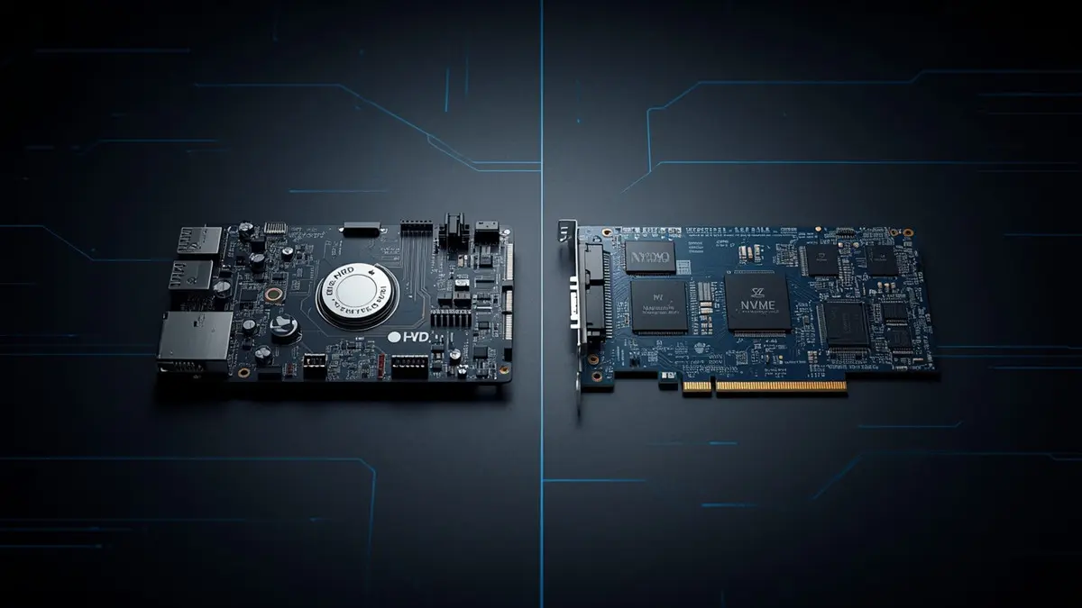
HDD PCB vs SSD PCB Comparison: Structural and Functional Differences
Both are PCBs, but the design priorities could not be more different:
| HDD PCB | SSD PCB | |
|---|---|---|
| Storage technology | Magnetic storage on rotating platters | NAND flash |
| Main functions | Drive control, power, interfaces, motor control | Flash management, controller, power, data interfaces |
| Mechanical interaction | Supports a mechanical storage device | No rotating mechanism |
| Design concerns | Power stability, controller compatibility, motor electronics | High-speed signal integrity, memory compatibility, thermal |
| Components | Controller, power devices, interface | NAND packages, controller, optional DRAM, power/interface |
| Testing | Board-level + drive-level functional verification | Board-level + storage and interface validation |
Treating an HDD board and an SSD board as the same kind of manufacturing job is a mistake. The materials, components, layout constraints, test fixtures, and acceptance criteria are different and have to be defined separately.
How These Boards Get Designed and Manufactured
Whether you are buying bare boards or full assemblies, the work follows the same arc: engineering review, fabrication, assembly (if needed), inspection, electrical test, and acceptance. The sequence below is what actually happens on the shop floor.
1. Engineering review and DFM. A Design for Manufacturability review checks whether your data can be produced reliably with the chosen process. Concretely that means verifying the Gerber or ODB++ data, the outline, layer count and thickness, copper weight and trace geometry, drill sizes and plated-hole requirements, solder mask and surface finish, footprints and assembly clearances, and whether the BOM is consistent and available. If the design is impedance-controlled, the target values, stackup, dielectric properties, and tolerances have to be in the design documentation. Any proposed change gets reviewed and approved by you before we touch the tooling.
2. Bare-board fabrication. Once the data is approved, the board goes through material prep and inner-layer imaging, etching and inspection, lamination, drilling, plating, outer-layer imaging and etching, solder mask, surface finish and legend, then electrical test and final inspection. The exact sequence depends on the construction. And the material, copper thickness, layer count, and tolerances should come from your approved design — not from a generic idea of “what a hard drive PCB usually is.”
3. Assembly (when you need a populated board). For an assembled HDD PCB, scope extends to solder paste printing, SMT placement, reflow, through-hole assembly where required, AOI, X-ray for the applicable joints, programming if specified, and electrical/functional test. You do not need every inspection method on every board — the plan should match the package types, design risks, and your acceptance criteria.
4. Prototype validation and production release. Before volume, a prototype gets reviewed against the design and test plan: manufacturing data approval, prototype build, electrical and assembly inspection, engineering validation, your sample approval, pilot production, and a controlled release. A staged release catches design, assembly, and sourcing problems while they are still cheap to fix.
Specs to Pin Down Before You Order
The fastest way to cut quotation back-and-forth is a clear technical spec that says exactly what you want delivered. Use this checklist:
- Product scope — bare PCB, assembled PCBA, or something else.
- Board dimensions — length, width, outline, mechanical drawing.
- Layer count — number of copper layers and approved stackup.
- Board thickness — nominal value and tolerance.
- Base material — specified laminate.
- Copper weight — thickness per relevant layer.
- Trace/spacing — minimum geometry per the design.
- Drill — hole sizes, tolerances, plated or non-plated.
- Surface finish — ENIG, HASL, or approved alternative.
- Solder mask — color and process requirements.
- Electrical — supply rails, currents, interfaces, impedance where applicable.
- Components — BOM, part numbers, approved alternatives, programming.
- Assembly scope — SMT, THT, mixed, special handling.
- Testing — electrical test, AOI, X-ray, functional, acceptance criteria.
- Quantity — prototype, initial production, forecast.
- Documentation — drawings, revisions, inspection records, traceability.
- Delivery — schedule, packaging, labeling, destination.
There is no universal layer count or trace width for “an HDD PCB.” The right spec depends on the circuit, electrical loads, interfaces, thermal needs, mechanical constraints, and tolerances. Do not copy a parameter from another product’s datasheet just because it is there — work from your approved design, and when something is unclear, ask the design engineer rather than guessing. For a new design, early collaboration with the manufacturer decides whether your construction is actually manufacturable.
How These Boards Are Tested
The acceptance criteria depend on what you are buying. A bare board, an assembled board, and a full drive are three different test problems.
Bare PCB electrical test checks continuity and isolation to catch unintended opens and shorts, plus dimensional, hole, registration, solder mask, and finish checks. Important caveat: passing a bare-board test says nothing about whether the populated board will actually work.
PCBA inspection covers AOI for component presence and soldering defects, X-ray for hidden joints, visual checks on connectors and critical parts, verification of part numbers and placement, and review of soldering records — scoped to the board’s real risks.
Electrical and functional test may add power-rail checks, verification of specified electrical parameters, interface checks, programming verification, and functional tests against an approved fixture. Full drive-level validation needs the mechanical drive, the right firmware, and a dedicated test environment — do not assume it is included in a standard PCB or PCBA quote.
Quality documents to request up front: electrical test records, PCBA inspection records, material and component traceability, approved BOM and revision history, nonconformance records, functional test results, and compliance documentation. Agree on these before production starts, not after the first shipment lands.
Why Hard Drive PCBs Fail
Most failures trace back to electrical damage, component failures, assembly defects, environmental exposure, or a fault elsewhere in the drive. A few common patterns:
| Symptom | Likely cause | Next step |
|---|---|---|
| No power response | Input problem, protection component failure, power fault | Check input conditions, get qualified diagnosis |
| Visible burnt parts | Electrical surge, short, component failure | Stop applying power, inspect the affected circuit |
| Intermittent operation | Connector issue, soldering defect, unstable power | Review power, connections, test records |
| Drive not detected | PCB, interface, firmware, or mechanical issue | Diagnose before replacing parts |
| Abnormal noise | Mechanical damage, drive-level fault | Stop repeated testing, get specialist assessment |
| Fails after assembly | Wrong component, soldering defect, assembly damage | Review BOM, inspection, electrical test |
These are starting points, not verdicts. A drive that does not spin or appear in the host does not automatically have a dead PCB. For OEM work, failure analysis has to separate fabrication defects from assembly defects, component failures, design problems, and faults that originate outside the board. A structured process — evidence collection, visual inspection, electrical measurement, component verification, root cause, corrective action, documented retest — is what turns a diagnosis into a fix.
Can You Replace a PCB Without Losing Data?
Replacing the PCB does not restore access to the data, and it is not a universal procedure. On some HDD platforms a replacement board needs compatible firmware or a transfer of drive-specific ROM/calibration data; the requirements vary by drive family and revision. Before you swap anything, confirm the complete drive model and hardware identifiers, the PCB part number and revision, the firmware and drive-specific data requirements, whether the original board is even repairable, and whether the drive has mechanical damage.
A board that looks identical is not necessarily electrically or operationally compatible. ROM transfer — moving drive-specific information from the original board to a compatible replacement — is only supported and required on certain platforms, and getting it wrong can make recovery worse. If the drive holds important data, do not keep power-cycling it or swapping boards on a hunch; when the failure cause is uncertain, get a professional assessment. And to be clear: these repair concerns are separate from the production requirements for a newly designed board.
What Determines the Price
Cost follows design, production scope, components, testing, quantity, and delivery — not a generic “per board” number. A reliable quote separates the categories that actually apply to your project:
- Layer count and construction — material use, process complexity, fabrication time.
- Dimensions and copper — material consumption and processes.
- Fine features and tolerances — tighter controls, more inspection.
- Surface finish — different process and material costs.
- Component sourcing — critical IC availability and MOQs move pricing.
- Assembly complexity — component count, package types, placement density.
- Testing — fixtures, programming, inspection, functional verification.
- Quantity — prototypes and production have different cost structures.
- Delivery schedule, packaging, logistics — expediting and handling costs.
Ask the supplier to break out engineering/NRE charges, bare-board fabrication, component sourcing fees, assembly, programming and testing, packaging and shipping, and tooling or fixture charges. Then compare quotes on the same technical scope, BOM revision, quantity, test coverage, and delivery terms. The cheapest number on paper is a bad deal if it skips necessary inspection or sneaks in unapproved component alternatives.
How to Choose a Manufacturer
Price and advertised capability are where evaluation starts, not where it ends. Verify the supplier can actually meet your technical, quality, sourcing, and delivery requirements.
Engineering and DFM. A capable supplier reviews your data, flags inconsistencies, asks for missing specs, and documents proposed changes. Ask how they handle data review, BOM verification, engineering changes, prototype feedback, revision control, and approval before design changes.
Scope. Not every shop does everything. Confirm whether they provide bare-board fabrication, SMT and THT assembly, component sourcing, programming, electrical test, and functional verification — and whether the work is in-house or subcontracted.
Quality and traceability. Get specifics on inspection methods, test coverage, component traceability, process documentation, and nonconformance handling. Verify certifications against the actual certificate, its scope, issuing body, and validity — a generic “we are ISO certified” claim proves nothing about your product.
Component sourcing risk. Parts with long lead times, limited availability, or end-of-life status can stall a build. Evaluate distributor sourcing, authenticity controls, lifecycle and obsolescence monitoring, alternate-part approval, lot traceability, and how quickly they flag shortages. No substitute gets introduced without the approval your engineering and quality procedures require.
Prototype vs. volume. For prototypes, you want strong engineering communication and fast issue resolution. For volume, look at repeatability, process controls, material availability, batch traceability, yield monitoring, and change management.
A practical evaluation checklist: Can they review files and resolve DFM issues? Can the construction and tolerances be supported? Are the required packages and processes supported? Can they follow the approved BOM and substitution rules? Are inspection methods and acceptance criteria documented? Can they perform the required electrical and functional tests? Can materials, revisions, and batches be traced? Are engineering questions and changes documented? Can they support the schedule and volume? Are quotation scope, lead time, packaging, and delivery clear? Working through these beats picking a supplier on a slogan.
What to Put in an RFQ
A complete RFQ lets a manufacturer assess feasibility and price before production starts. Prepare:
Technical files — Gerber or ODB++, fabrication drawing and stackup, schematic and assembly drawing, a BOM with full part numbers, pick-and-place data, and programming/test procedures (where appropriate to share).
Manufacturing requirements — bare PCB or assembled PCBA, dimensions/layers/thickness/copper/material, surface finish and solder mask, assembly processes and sourcing expectations, electrical and inspection/test requirements, quality and documentation requirements.
Commercial requirements — prototype and production quantities, forecast, target delivery date, packaging and labeling, shipping destination and terms, and the quotation breakdown you want.
Revision and approval — current design revision, approved BOM revision, engineering-change approval process, component substitution policy, and sample acceptance / production release criteria.
If a piece of information is not available yet, say so as an open engineering item instead of letting a supplier assume it.
About This Guide
This article is published by HAODA ELECTRONIC CO.,LIMITED. We manufacture PCBs and PCBAs, including hard drive control boards. For a project-specific assessment, send your fabrication files, BOM, quantity, assembly requirements, and test specifications — the engineering review will define the manufacturing scope, resolve open technical questions, and identify what is needed for an accurate quotation.
Contact: Email — pcb@pcbcoming.com
Confirm feasibility, scope, lead time, and pricing for each project before committing to a schedule.
FAQ
What is a hard drive PCB board? The circuit board that handles the electronic control, power management, and communication functions of a hard disk drive. Its exact components depend on the drive design.
What’s the difference between HDD and SSD PCBs? An HDD PCB supports the electronics of a mechanical drive, including motor control. An SSD PCB serves NAND flash, its controller, power, and interfaces. Different architectures, different manufacturing requirements.
Can I replace a hard drive PCB with another board from the same model? Not always. Revision, component population, firmware, and drive-specific data all affect compatibility. Verify the identifiers and platform requirements first.
Does replacing the PCB recover lost data? No. It only helps if the failure is on the board and the replacement is compatible with the drive-specific data. Diagnosis comes first.
What are the common symptoms of a faulty HDD PCB? No power response, visible electrical damage, or failure after a surge. But the same symptoms can come from other faults, so diagnose before replacing parts.
What files are needed for a custom hard drive PCB quote? Gerber or ODB++, fabrication drawings, BOM, quantities, board specs, and inspection/testing requirements. Assembly projects also need assembly drawings and placement data.
What’s the difference between PCB fabrication and PCBA? Fabrication makes the bare board; PCBA adds the components and soldering. Programming and testing may be included in the PCBA scope if agreed in the quote.
How are hard drive PCBs tested? Bare-board continuity and isolation checks, AOI, X-ray for applicable assemblies, power checks, interface verification, and functional testing per the approved requirements.
What drives hard drive PCB cost? Construction, material, tolerances, component availability, assembly complexity, test requirements, quantity, and delivery schedule. A project-specific RFQ is the only way to get an accurate price.
Can a manufacturer supply both bare boards and assembled hard drive PCBs? Some do. Confirm the supplier’s actual process scope, sourcing, testing capability, and relevant experience for your specific design.
What quality documents should I ask for? Electrical test results, inspection records, material and component traceability, revision-controlled production documentation, and functional test results.
How can OEMs reduce hard drive PCB supply-chain risk? Approved BOM, verified component lifecycle, defined substitution rules, traceability requirements, and agreed engineering-change procedures before production.
About Author
David Chen LinkedIn Profile
David Chen is a Senior RF/PCB Process Engineer at HAODA ELECTRONIC CO.,LIMITED., with over 12 years of experience in high-frequency PCB fabrication, impedance-controlled stack-up design, and Rogers/PTFE laminate processing. He also boasts an extensive professional background in PCBA manufacturing, PCBA testing, and PCBA optimization, with specialized expertise in high-precision PCBA fault analysis and rigorous PCBA reliability testing. The author has worked with high-layer-count server PCB fabrication, ultra-low-loss backplane stackups, and thermo-mechanical reliability optimization for AI infrastructure projects involving 112G and 224G PAM4 architectures. Skilled in complex circuit design and cutting-edge advanced PCB manufacturing processes, he delivers solutions that elevate product durability and performance across industrial applications. His technical articles focusing on PCBA manufacturing workflows and testing methodologies are widely cited by industry peers and technical platforms, and have gained attention and recognition from industry colleagues.