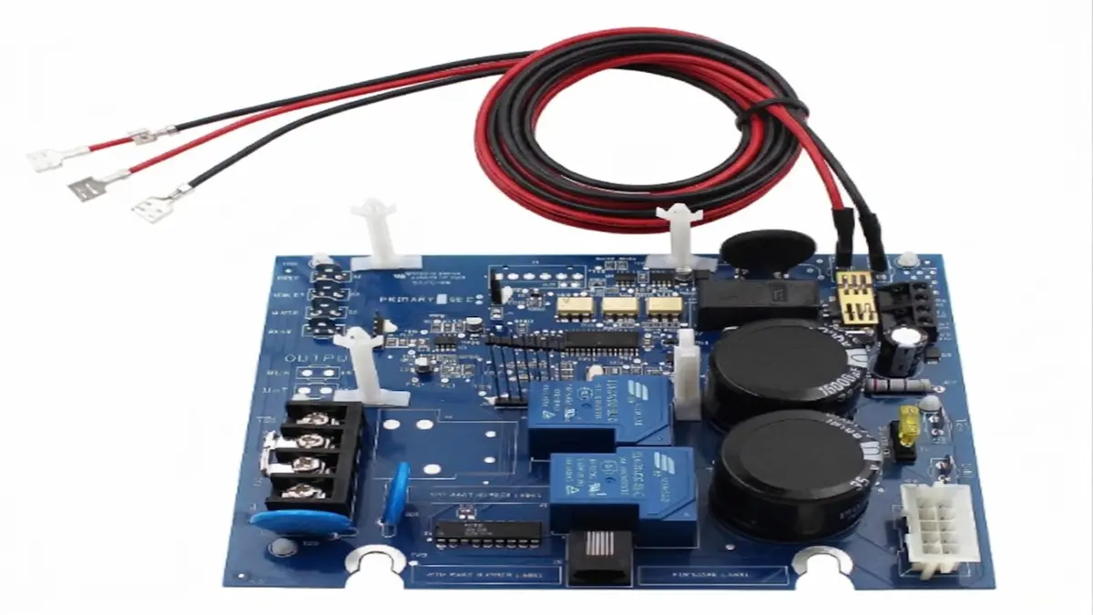
A PCBA Functional Tester verifies whether an assembled circuit board performs its intended functions under controlled operating conditions. It can check power rails, firmware, analog signals, digital I/O, communication interfaces, current consumption, and system responses. Unlike ICT, which focuses on circuit-level integrity, FCT evaluates the PCBA as a working electronic system.
What Is a PCBA Functional Tester and How Does It Differ From ICT?
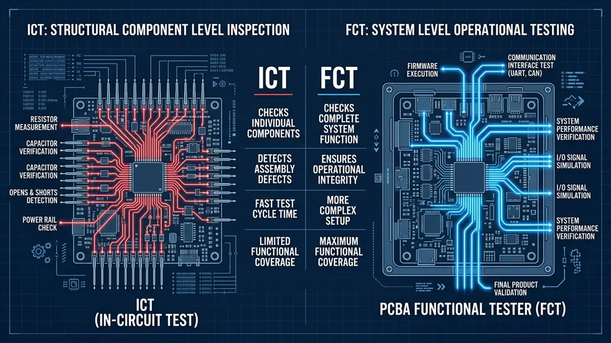
Comparison between ICT and PCBA Functional Tester in Manufacturing
ICT verifies whether components and electrical connections are correctly assembled; a PCBA Functional Tester verifies whether the completed PCBA behaves according to its functional specification.
This distinction matters because a board can pass electrical inspection and still fail when powered. Firmware errors, incorrect configuration, communication faults, timing problems, sensor failures, and load-dependent behavior may not be adequately detected by conventional component-level testing.
A practical PCBA testing strategy can divide the responsibilities as follows:
| Test Method | Primary Purpose | Typical Coverage |
|---|---|---|
| SPI/AOI | Assembly-process inspection | Solder paste, placement, polarity, visible solder defects |
| X-Ray/AXI | Hidden-joint inspection | BGA, QFN and other concealed solder joints |
| ICT | Electrical/structural verification | Opens, shorts, selected components and nets |
| Flying Probe | Flexible electrical testing | Opens, shorts and selected circuit measurements |
| FCT | Functional verification | Power, firmware, I/O, communication and system behavior |
The most useful question is therefore not “ICT or FCT?” but which failure modes need to be detected at each production stage.
For example, an IoT controller could use the following FCT sequence:
Power input → voltage-rail check → MCU boot → UART response → sensor reading → USB/Ethernet communication → current-consumption check → result logging.
An automotive controller may require a more controlled sequence:
Input power → power sequencing → MCU initialization → CAN/CAN-FD communication → simulated sensor input → output response → diagnostic communication → shutdown behavior.
For a consumer product, successful boot and interface communication may be the main production criteria. Automotive and industrial products generally require more carefully defined operating limits, diagnostic states, communication timing, and fault-response behavior.
The important engineering principle is that FCT should test functions that represent real product risks, rather than simply increasing the number of test steps.
How Can a PCBA Functional Tester Achieve High Throughput?
FCT throughput is determined by the complete station cycle—not just the electronic measurement time. Loading, fixture contact, initialization, testing, data logging, unloading, retesting, and maintenance all affect effective production capacity.
Consider a 75-second production FCT cycle:
| Operation | Example Time |
|---|---|
| PCBA loading | 8 s |
| Fixture closing/contact | 5 s |
| Power-up and initialization | 10 s |
| Functional test sequence | 40 s |
| Data recording | 4 s |
| Unloading | 8 s |
| Total | 75 s |
Theoretical capacity is:
3,600 ÷ 75 = 48 PCBAs/hour
If production requires 80 PCBAs/hour, two parallel stations provide approximately:
2 × 48 = 96 PCBAs/hour theoretical capacity
The practical output will be lower after accounting for operator handling, retests, fixture maintenance, equipment downtime, and occasional test-program interruptions.
Test sequencing can reduce cycle time
A good FCT sequence does not necessarily execute every operation one after another.
Independent measurements can sometimes be performed concurrently. Instrument initialization can overlap with PCBA boot time. Long diagnostic operations can be moved away from the critical production path when they are not required on every unit.
The test program should also distinguish between:
- Required production tests
- Diagnostic tests
- Engineering validation tests
- Sampling/reliability tests
This prevents engineering-level validation from unnecessarily becoming a production bottleneck.
Should you use a bed-of-nails fixture or flying probe?
A bed-of-nails FCT fixture provides simultaneous access to multiple test points and is attractive when the PCB design is stable and production volume justifies dedicated tooling.
A flying-probe tester uses programmable probes instead of a dedicated large contact fixture. It is generally more flexible for prototypes, NPI, low-volume production, and frequently changing PCB designs.
The decision should consider:
Annual volume + PCB revision frequency + test-point accessibility + target cycle time + fixture investment + product lifetime.
Fixture maintenance also deserves attention. Pogo pins should be inspected for contamination, mechanical wear, inconsistent contact, and rising contact resistance. Cleaning frequency should reflect actual production conditions, while replacement should be based on probe specifications, measured wear, and accumulated cycles rather than a universal replacement interval.
Which Interfaces Should a Modern PCBA Functional Tester Support?
A functional tester should reproduce the interfaces that the PCBA uses during normal operation, including USB, Ethernet, CAN/CAN-FD, UART, SPI, I²C, GPIO, JTAG, and, when necessary, PCIe or other high-speed serial interfaces.
Common PCBA functional testing requirements include:
- USB: enumeration, identification, data transfer and power behavior
- Ethernet: link establishment, packet communication and device identification
- CAN/CAN-FD: frame transmission, reception and diagnostic communication
- UART: bootloader, console and firmware verification
- SPI: flash, DAC, ADC and peripheral communication
- I²C: sensors, EEPROMs, PMICs and peripheral devices
- GPIO: digital input/output response
- JTAG: programming, debugging and boundary-scan
- PCIe/SerDes: link training and high-speed communication
The interface should be connected through a fixture architecture that does not unintentionally alter the signal being tested.
For high-speed signals, the FCT fixture should consider:
- Controlled impedance
- Differential-pair routing
- Short electrical paths
- Appropriate connectors
- Continuous signal-return paths
- Grounding strategy
- Cable length
- Crosstalk
- Fixture parasitic capacitance and inductance
A common production mistake is to validate a high-speed interface with a simple “link established” result and assume that this proves signal quality.
It does not necessarily do so.
When signal margin is important, engineering validation may require TDR, eye-diagram analysis, or BERT testing. These methods can reveal impedance discontinuities, excessive jitter, attenuation, or other high-speed channel problems that a basic functional handshake may not expose.
When should JTAG or boundary-scan be used?
JTAG/boundary-scan becomes particularly useful when dense BGA packages and high component density make conventional physical probing difficult.
Rather than requiring a physical probe on every internal digital connection, boundary-scan-capable devices can provide electronic access to selected interconnects through the scan chain.
This makes boundary-scan valuable for:
- High-density digital boards
- BGA-heavy PCBAs
- Limited physical test access
- Digital interconnect verification
- Device programming
- Board-level structural diagnosis
It is best treated as a complement to FCT. Power systems, analog circuits, sensors, RF functions, mechanical interfaces, and application-level behavior may still require physical stimulation and measurement.
How Should FCT Test Coverage, Diagnostics, and Repair Be Designed?
A useful FCT system should report more than PASS or FAIL. Every important test item should have a defined stimulus, measurement method, acceptance limit, failure code, and diagnostic path.
Start with a test coverage matrix.
| Functional Block | Test | Measurement | Acceptance | Failure Code |
|---|---|---|---|---|
| Power input | Input voltage | Voltage | Defined range | PWR_IN |
| DC rails | Rail verification | Voltage | Upper/lower limits | PWR_05 |
| MCU | Boot test | Response | Expected response | MCU_BOOT |
| CAN | Communication | Frame response | Expected ID/data | CAN_COM |
| ADC | Analog input | Digital reading | Defined window | ADC_01 |
| USB | Enumeration | Device response | Expected device | USB_ENUM |
A useful repair workflow is:
FCT failure → identify failed function → isolate module → verify supply/interface → inspect assembly → replace suspected component → retest.
For example:
CAN communication failure → verify power rail → check CANH/CANL termination → inspect connector and solder joints → check transceiver activity → replace suspected transceiver → rerun FCT.
This diagnostic granularity can significantly reduce unnecessary component replacement.
What should an FCT result record contain?
At minimum, a traceable production record should include:
- PCBA serial number
- Test timestamp
- Station ID
- Test-program version
- Firmware version
- Test-item ID
- Instrument/channel
- Measured value
- Upper/lower limit
- PASS/FAIL status
- Error code
- Retest count
The data can then be connected with MES, ATE, production databases, or quality-analysis systems.
The real value appears when FCT results are correlated with previous inspection stages. For example:
AOI defect location → ICT electrical failure → FCT communication failure → repair result
This creates a traceability chain that can help distinguish assembly defects from component, firmware, design, or test-system problems.
A test station that records only “PASS” or “FAIL” provides much less engineering value than one that preserves the actual measurements and failure conditions.
What Are the Main PCBA Functional Tester Costs and How Should You Calculate ROI?
The cost of an FCT solution includes the tester, instruments, fixture, software, engineering integration, maintenance, calibration, and production support. ROI should therefore be calculated using total ownership cost rather than equipment price alone.
Typical cost categories include:
- FCT hardware
- Power supplies and electronic loads
- DMM/DAQ/oscilloscope or specialized instruments
- Custom fixture
- Probes and connectors
- Test software development
- Firmware/programming integration
- MES/API integration
- Engineering labor
- Calibration and maintenance
- Spare parts
- Production support
For a simplified example, assume:
- Manual test cost: $1.20/PCBA
- Automated FCT labor-equivalent cost: $0.35/PCBA
- Annual volume: 100,000 PCBAs
- FCT investment: $50,000
Annual direct saving:
($1.20 − $0.35) × 100,000 = $85,000
Simple payback:
$50,000 ÷ $85,000 ≈ 0.59 years
This is a planning example, not a universal industry benchmark. A serious ROI calculation should also consider:
First-pass yield + test escape reduction + labor + throughput + retest rate + fixture maintenance + downtime + engineering-change cost.
What should you evaluate when selecting an FCT supplier?
Price should not be the only procurement criterion.
Compare suppliers on:
- Fixture engineering capability
- Prototype/NPI support
- Test-program development
- Debugging capability
- Hardware customization
- Second-development capability
- API/MES integration
- Instrument compatibility
- Documentation
- Calibration traceability
- Spare-parts support
- Production ramp assistance
- Quality-system controls
The software architecture is equally important. A maintainable system should separate instrument drivers, test sequences, product configuration, result storage, and reporting. This makes it easier to support firmware revisions and multiple product variants without rewriting the entire test application.
For measurement equipment, calibration should be controlled through documented records containing the instrument identification, calibration date, due date, applicable standard, and result. The actual calibration interval should follow the instrument manufacturer’s specification and the applicable quality procedure.
How Should a PCBA Functional Test Program Be Connected to the Manufacturing Process?
FCT should be treated as part of the PCBA manufacturing quality system rather than an isolated final inspection step.
A robust test architecture can follow:
PCB Design → DFT Review → SMT Assembly → SPI/AOI → X-Ray Where Required → ICT/Flying Probe → Programming → FCT → Repair → Retest → Final Inspection
The exact sequence depends on the product and failure risks.
For example, an assembly-related defect is usually cheaper to detect close to the SMT process than after firmware programming and final functional testing. Conversely, a firmware or communication problem may only become visible once the PCBA is powered and operated.
This is why the best PCBA testing strategy assigns each test method a specific question:
- AOI: Was the component assembled correctly?
- ICT: Are the accessible electrical structures correct?
- Boundary scan: Can digital interconnects be verified electronically?
- FCT: Does the assembled product perform its intended function?
- Reliability testing: Does it continue to perform after defined environmental or stress exposure?
The result is a layered test system rather than several disconnected inspection machines.
How Can You Start a PCBA Functional Tester Project?
Start with a representative PCBA, defined functional requirements, target cycle time, interface list, and expected production volume. A small POC can expose fixture-access, software, measurement, and throughput issues before full-scale automation.
A useful FCT RFQ should include:
- Schematic
- PCB layout/CAD or Gerber data
- BOM
- Firmware version
- Programming requirements
- Required interfaces
- Functional test specifications
- Input/output limits
- Target cycle time
- Required production capacity
- Expected test coverage
- Acceptable false-fail/retest rate
- Production volume
- MES/ATE requirements
- Budget range
- Required delivery schedule
If available, representative failed PCBAs are also valuable because they allow the test engineer to evaluate whether the proposed test system can actually distinguish common production failures.
For manufacturers evaluating a complete PCBA functional testing program, Shenzhen Haoda Circuit Technology Co., Ltd. can support PCB assembly, test planning, functional verification, and production implementation. Contact pcb@pcbcoming.com or visit PCBcoming.com.
Procurement FAQ:
1. Can the supplier develop a complete PCBA functional test system from our specifications?
Yes, but buyers should verify the actual scope before placing an order. Ask whether the supplier can handle fixture design, test-program development, instrument integration, firmware programming, interface testing, data logging, and production debugging. A supplier that only provides a fixture may not be sufficient for a complex PCBA Functional Tester project.
2. What information should I provide for an FCT quotation?
Provide the BOM, schematic, PCB data, firmware version, functional test specification, interface list, target cycle time, annual volume, required coverage, acceptable false-fail/retest rate, and delivery requirement. Providing representative samples and known failure cases can make technical evaluation and quotation more accurate.
3. How should I compare the price of different PCBA functional testing suppliers?
Do not compare only the initial equipment quotation. Compare fixture cost, software development, engineering hours, instrumentation, MES/API integration, calibration, spare parts, maintenance, support, and future product-change costs. The lowest initial price may not produce the lowest total cost of ownership.
4. What FCT cycle time should I specify in an RFQ?
Specify the required seconds per PCBA and the required boards/hour, rather than simply asking for a “high-speed tester.” Ask the supplier to provide a cycle-time breakdown covering loading, fixture contact, initialization, functional measurements, communication tests, data logging, unloading, and retest handling.
5. How can I verify whether an FCT supplier can handle high-speed interfaces?
Ask for the supplier’s proposed test architecture for interfaces such as USB 3.x, Ethernet, PCIe, SerDes, or other high-speed links. The evaluation should cover controlled-impedance cabling, connector selection, grounding, differential routing, fixture length, and—when required—eye-diagram, TDR, or BERT validation. For dense digital boards, also ask whether JTAG/boundary-scan can reduce physical test access requirements.
About Author
David Chen https://www.linkedin.com/in/pcbcoming
David Chen boasts an extensive professional background in PCBA manufacturing, PCBA testing, and PCBA optimization, with specialized expertise in high-precision PCBA fault analysis and rigorous PCBA reliability testing. The author has worked with high-layer-count server PCB fabrication, ultra-low-loss backplane stackups, and thermo-mechanical reliability optimization for AI infrastructure projects involving 112G and 224G PAM4 architectures. Skilled in complex circuit design and cutting-edge advanced PCB manufacturing processes, he delivers solutions that elevate product durability and performance across industrial applications. His technical articles focusing on PCBA manufacturing workflows and testing methodologies are widely cited by industry peers, research institutions, and technical platforms, solidifying his reputation as a recognized technical authority in the global circuit board manufacturing sector.