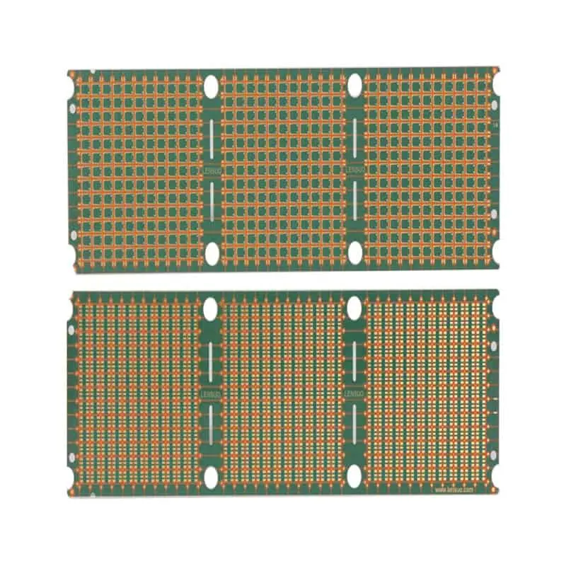
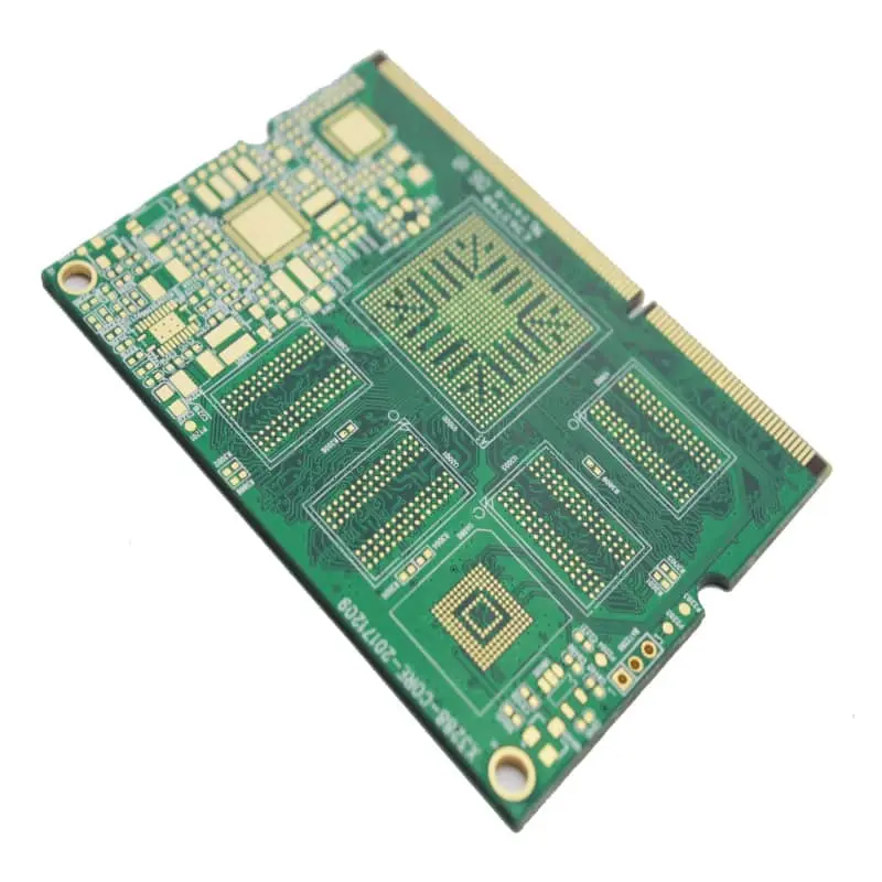
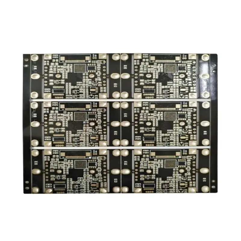
What RT/duroid 5870 Actually Is: Composition, Dk/Df, and Laminate Options
Rogers RT/duroid 5870 is a glass‑microfiber‑reinforced PTFE‑based high‑frequency laminate positioned in the ultra‑low‑loss segment of Rogers’ RF material portfolioRogers Cor…. Instead of relying on generic product‑line summaries, successful material selection starts with understanding its fundamental makeup and real‑world performance boundaries. Its composite construction delivers isotropic electrical behaviour, with a nominal dielectric constant (Dk) of 2.33 ± 0.02 and dissipation factor (Df) of 0.0012 at 10 GHz.
A common design pitfall is treating the single‑sheet nominal Dk value as universal across all frequencies. While performance remains stable at lower RF bands, both Dk and Df exhibit measurable drift moving toward millimetre‑wave bands. Lot‑to‑lot batch tolerances further shift real‑world impedance and phase response; engineers who ignore these variations risk simulation‑to‑hardware mismatch. Always reference the latest official datasheet rather than legacy web‑published parameter values.
RT/duroid 5870 ships in a broad range of dielectric thicknesses spanning from several mils up to multi‑dozen‑mil heavy cores, paired with two primary copper‑foil families: electrodeposited (ED) copper for general‑purpose production and rolled copper for minimum conductor‑loss millimetre‑wave circuitsRogers Cor…. Copper‑foil choice directly shapes insertion‑loss performance, copper peel strength, and overall manufacturability. Rolled copper cuts conductor loss but comes with higher material cost and tighter handling limits. For every project, tie foil grade, dielectric thickness, and tolerance together in stack‑up documentation before releasing designs to fabrication.
Thermal Reliability, CTE, and Fabrication Realities on the Shop Floor
Electrical specifications only tell half the story; long‑term hardware success hinges on thermal stability and practical PCB manufacturability. The Z‑axis coefficient of thermal expansion (CTE) of RT/duroid 5870 heavily governs plated‑through‑hole reliability under repeated thermal cycling. Multiple lead‑free reflow cycles introduce dimensional shift risk; designers must account for material expansion to avoid barrel cracking and registration drift. Though moisture absorption is very low for this PTFE composite, prolonged humid exposure still creates minor Df shifts that matter for high‑sensitivity receiver chains. Continuous high‑temperature operating conditions also demand evaluation for slow performance drift over service life.
PTFE laminates require special pre‑treatment for reliable hole metallization. Fabrication shops must implement plasma or sodium‑naphthalene activation to achieve adequate copper adhesion on hole walls; standard FR‑4 desmear recipes will fail on pure PTFE surfaces. Drill feed‑rate settings, desmear process windows, lamination temperature‑time profiles, and flow‑gel management for large‑area metallization all differ significantly from epoxy‑based hydrocarbon materials. Validated peel‑strength testing is essential to qualify production runs.
North‑American PCB‑factory capacity reshoring and additional process‑certification burdens for defence‑oriented programs further affect project timelines. Generic marketing claims of “excellent stability” add no value: when qualifying a board house, ask for actual process‑window data, historical build records for RT/duroid 5870, and cross‑section reports from previous comparable jobs rather than only reviewing compliance certificates.
Rogers 5870 vs. the Alternatives: PTFE, Hydrocarbon, and Design Trade‑offs
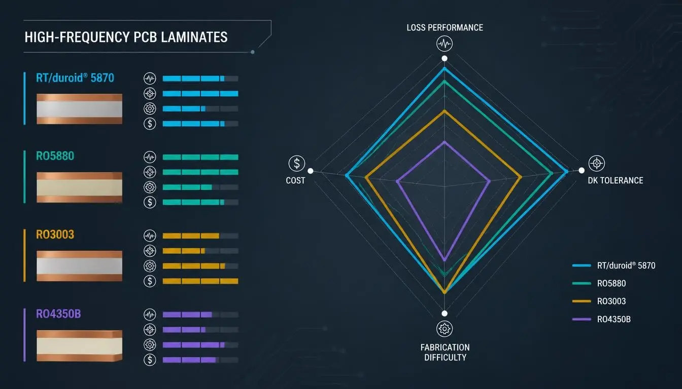
Rogers RT/duroid 5870 Composition, Dk/Df and Laminate Options
Selecting RT/duroid 5870 should never be automatic. Engineers must weigh it against competing PTFE materials (RT/duroid 5880, RO3003) and high‑performance hydrocarbon laminates including RO4350B, RO4835, plus equivalent offerings from Isola and Taconic. Decision‑making should evaluate five core dimensions: signal‑loss performance, Dk tolerance consistency, thermal stability, total landed cost, and fabrication difficulty.
RT/duroid 5880 delivers marginally lower loss at higher frequency but commands a higher premium. Hydrocarbon‑family boards simplify PCB processing (no PTFE activation steps), shorten fabrication cycles, and lower per‑unit cost, yet cannot match the ultra‑low Df of reinforced PTFE at millimetre‑wave frequencies. The practical design rule emerges: pay the PTFE premium when system‑level link‑budget constraints cannot tolerate higher hydrocarbon‑material loss; switch to hydrocarbon alternatives whenever loss budgets are more forgiving and cost and throughput priorities rise.
Simulation workflows require extra discipline when working with RT/duroid 5870. Simply importing static datasheet Dk/Df numbers yields inaccurate results. Designers must deploy frequency‑dependent material models, apply correction terms for copper‑foil surface roughness, and allocate impedance margin to accommodate both frequency‑driven Dk drift and manufacturing batch variation. Without these adjustments, simulated phase and impedance predictions diverge significantly from measured hardware performance.
Demand Outlook: Which Application Segments Will Drive Growth
Market growth for RT/duroid 5870 is segmented by vertical use‑case rather than a uniform overall market expansion. In aerospace and defence, phased‑array radar, electronic‑warfare subsystems, and satellite‑communication payloads represent established, stable‑volume replacement demand alongside selective new‑program growth. Millimetre‑wave automotive radar operating across the 76–81 GHz band creates fresh incremental demand, though adoption varies by platform generation. Additional growth vectors include 5G millimetre‑wave backhaul hardware and SATCOM ground terminals, as well as high‑precision test‑and‑measurement instrumentation.
Not every trend increases laminate consumption. Antenna‑in‑package architectures and advanced multi‑layer stack‑ups can reduce the total area of standalone RT/duroid 5870 per unit system, even as overall RF‑system count rises. Procurement and engineering teams must distinguish between steady replacement volume versus genuine new‑design incremental demand for accurate capacity forecasting.
Regional supply‑chain shifts further shape market dynamics. Ongoing North‑American PCB‑manufacturing reshoring, export‑control compliance requirements, and government‑program funding cycles introduce order‑volatility risk. Project schedules need to account for these macro‑factors, as defence‑funded contract timing can swing near‑term laminate demand sharply up or down.
Supply, Pricing, Lead Times, and Lifecycle Risk
PTFE‑type high‑frequency laminate production remains geographically concentrated. Lead times fluctuate with global order cycles; pricing varies with base‑metal copper costs, PTFE‑resin raw‑material expenses, and order batch scale. For multi‑year long‑duration programs, proactive volume locking with authorised distributors mitigates availability shocks. Every high‑risk program should formally define secondary‑source strategies and acceptable equivalent‑substitute materials, documented within engineering change control. There are clear price thresholds between low‑volume prototype‑scale pricing and volume‑production quotes; procurement teams should clarify these tier‑break points early in RFQ cycles.
Lifecycle obsolescence represents an under‑discussed but serious project risk. Program managers need to confirm formal long‑term supply commitments for RT/duroid 5870, review historical revision or discontinuation events for related material families, and maintain design‑file portability. If material supply status shifts mid‑program, pre‑validated alternate‑material stack‑ups prevent costly schedule slips. Avoid relying solely on manufacturer sales assurances; request formal product‑lifecycle documentation as part of supplier qualification.
Next Steps: Move from Specification to Verified Hardware
If you are evaluating RT/duroid 5870 for your upcoming project, follow three parallel actionable workflows for design, procurement, and program management.
For RF designers: Request the latest official datasheet and frequency‑dependent simulation material‑model files. Schedule stack‑up review sessions with your PCB fabricator and order small impedance‑coupon validation test boards before full layout release. Validate modelled loss and phase performance against measured coupon data.
For procurement specialists: Secure formal tiered pricing schedules and current lead‑time forecasts from authorised distributors. Document volume‑lock options and secondary‑source substitution rules within purchasing specifications.
For program managers: Obtain written long‑term‑supply‑status statements for RT/duroid 5870 and maintain pre‑approved alternate‑material contingency plans for hardware‑revision fallback.
These steps reduce surprises and keep high‑frequency projects on schedule.
Frequently Asked Questions
Q: What is Rogers RT/duroid 5870 made of, and what dielectric constant does it offer?
A: RT/duroid 5870 is glass‑microfiber‑reinforced PTFE composite laminate with nominal Dk 2.33 ± 0.02 .
Q: How do Dk and Df of Rogers 5870 change from 1 GHz up to millimetre‑wave frequencies?
A: Properties stay very stable at lower RF bands, but both Dk and Df show measurable drift at millimetre‑wave frequencies. Always use frequency‑aware simulation models and plan for lot‑to‑lot tolerance.
Q: Is Rogers 5870 a good fit for automotive radar and 5G mmWave infrastructure?
A: Yes for high‑performance 76–81 GHz radar and 5G millimetre‑wave backhaul hardware, provided loss budgets justify PTFE‑material premium; hydrocarbon alternatives may suffice for less‑demanding variants.
Q: How does RT/duroid 5870 compare with RO4000‑series hydrocarbon laminates on loss, cost, and processability?
A: 5870 provides lower high‑frequency loss but demands specialised PTFE fabrication treatment and carries higher material expense. RO4000‑series materials process more easily at lower cost with higher Df at mm‑wave bands.
Q: What fabrication and processing guidelines should a PCB shop follow when building with 5870?
A: Shops must implement plasma or sodium‑naphthalene hole‑wall activation, adjust drilling, desmear, and lamination parameters away from FR‑4 recipes, and validate copper peel strength.
Q: What are current lead times and pricing trends for Rogers 5870 laminate?
A: Lead times shift with market cycles; pricing is copper‑ and volume‑dependent. Work with authorised distributors for real‑time tiered quotes and volume‑locking options.
Q: Is Rogers 5870 at risk of obsolescence, and how should teams plan for lifecycle risk?
A: Confirm formal long‑term supply documentation, define secondary sources and pre‑qualified substitute stack‑ups, and keep design files portable to mitigate potential future supply‑change risks.
About Author
David Chen LinkedIn Profile
David Chen is a Senior RF/PCB Process Engineer at Shenzhen Hongda Circuit Technology Co., Ltd., with over 12 years of experience in high-frequency PCB fabrication, impedance-controlled stack-up design, and Rogers/PTFE laminate processing. He also boasts an extensive professional background in PCBA manufacturing, PCBA testing, and PCBA optimization, with specialized expertise in high-precision PCBA fault analysis and rigorous PCBA reliability testing. The author has worked with high-layer-count server PCB fabrication, ultra-low-loss backplane stackups, and thermo-mechanical reliability optimization for AI infrastructure projects involving 112G and 224G PAM4 architectures. Skilled in complex circuit design and cutting-edge advanced PCB manufacturing processes, he delivers solutions that elevate product durability and performance across industrial applications. His technical articles focusing on PCBA manufacturing workflows and testing methodologies are widely cited by industry peers and technical platforms, and have gained attention and recognition from industry colleagues.