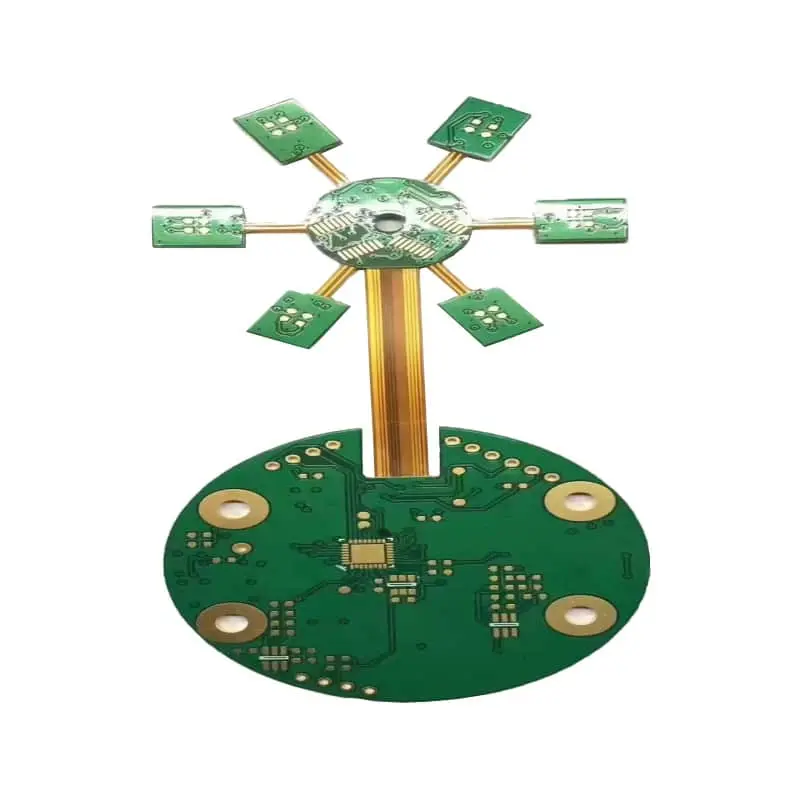
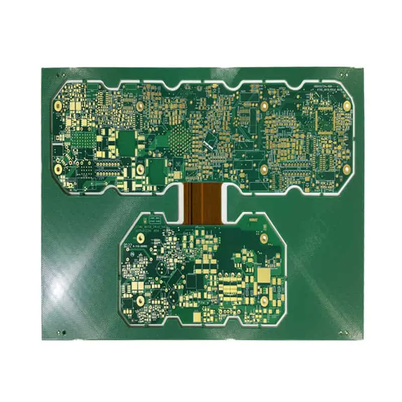
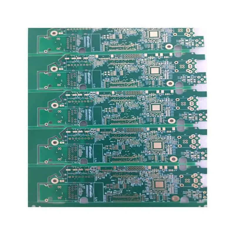
EGO 56‑V lithium‑ion battery packs power a wide range of popular cordless outdoor power tools, from lawn mowers and string trimmers to leaf blowers and chainsaws. At the heart of every EGO ARC‑Lithium battery sits the EGO battery PCB, a dedicated battery management system (BMS) board. This circuit board governs cell safety, power output, thermal monitoring and bidirectional communication between the battery pack, charger and power tool. Many online resources only offer vague introductions to this component. This article delivers practical, actionable knowledge covering part‑number matching, operational logic, fault troubleshooting, hands‑on replacement and purchasing decisions for home technicians and tool owners.
EGO Battery PCB Part Numbers, Fitment, and 56V Compatibility
Before repairing or purchasing a replacement board, confirming hardware compatibility is the top priority. EGO official OEM part numbers correspond to specific physical battery‑pack models, which further pair with different outdoor power‑tool units. Mismatched PCBs will trigger communication failures, prevent charging or stop tools from running even with physically identical battery housings.
Cross‑reference OEM part numbers against your existing battery‑pack model label. Verify which EGO tools including lawn mowers, string trimmers, blowers and chainsaws work with that specific battery hardware. Beyond part‑number lookup, visual inspection helps spot counterfeit replacement boards. Check silkscreen printing quality on the PCB surface, connector shape and pin layout, as well as official marking and anti‑counterfeit label details.
Many competing guides skip detailed cross‑reference tables and visual identification tips, leaving users guessing whether a replacement will fit. Double‑check both printed part codes and physical connector geometry; identical‑looking battery shells may contain non‑interchangeable BMS circuit boards. (Word count: 262)
How the EGO Battery BMS Board Works: Balancing, Protection, and Charger Communication
Functioning as the battery’s control brain, the EGO battery PCB executes several core BMS tasks. It manages passive or active cell balancing to keep individual lithium‑ion cell voltages closely matched across the 56‑V battery stack. The hardware enforces critical safety protection: over‑discharge cutoff, over‑current shutdown and real‑time temperature sampling via onboard thermistor and thermocouple circuits.
One less‑documented feature is bidirectional digital handshaking. The PCB exchanges status data with both the EGO charger and connected power tool. It shares temperature, cell‑voltage and state‑of‑charge readings; in return, it receives charging parameters and power‑demand instructions. Faults within this communication layer produce common real‑world symptoms: refusal to start charging, error‑code flashing on the charger, or power tools failing to recognise an otherwise physically intact battery pack. Understanding this handshake logic lays essential groundwork for later fault diagnosis. (Word count: 227)
Diagnosing EGO Battery PCB Faults: No‑Charge, Cutoff, and Sensor Problems
Troubleshoot your EGO battery by following observable symptoms instead of abstract circuit theory. Common failure signs include complete no‑charge response, repeated LED flash error codes, random mid‑job power cutoff, and sudden tool shutdown under heavy load.
Internal PCB component failures create distinct patterns. Blown MOSFET power switches lead to total loss of output or short‑circuit behaviour. Blown fuses produce complete electrical isolation between battery cells and external terminals. Failed thermistors send false temperature readings, triggering false thermal lock‑outs even at normal ambient temperature.
Follow a safe measurement workflow to isolate root causes. Distinguish problems originating from the lithium‑ion cell stack, defects on the BMS PCB itself, or faults located inside your EGO charger or power tool. Understand the operating limits and risks of attempting a dead‑battery pack reset; reset procedures cannot repair shorted or degraded physical cells and carry fire hazards when misused. Always prioritise personal safety when probing high‑voltage 56‑V battery assemblies. (Word count: 284)
EGO Battery PCB Replacement: Teardown, Pinout, Soldering, and Calibration
Replacing an EGO battery PCB demands strict safety discipline when working with high‑energy lithium‑ion cell assemblies. Begin by electrically isolating the cell stack to eliminate short‑circuit risk before disassembly.
Original EGO battery packs use potting compound for water‑resistant sealing. Carefully remove waterproof potting encapsulant without damaging battery cells or wiring harnesses. Study connector placement, official pin‑out diagrams and reference expected voltage and resistance values for each contact point. Practice proper desoldering and re‑soldering techniques for high‑current power tabs and signal connectors.
Physical board swap is not the final step. After fitting a new or replacement PCB, complete voltage calibration for the cell group. Watch out for controller lock‑out risks that can appear after hardware change‑over. Run full post‑swap validation tests to confirm charging, temperature sensing and power‑delivery functions work normally. Many third‑party tutorials skip potting handling, pin‑out reference and post‑replacement calibration; skipping these steps results in premature repeated failure of your repaired battery pack. (Word count: 281)
Repair vs Replace: Sourcing EGO Battery PCBs and Warranty Tradeoffs
Battery owners face three main options when an EGO battery fails: component‑level board repair, full battery‑pack replacement, or installation of an aftermarket replacement PCB. Each choice carries different cost levels, labour requirements and warranty implications.
Genuine OEM boards, aftermarket reproduction units and used pull‑off salvaged boards each come with unique benefits and risks. Original genuine parts maintain factory specifications but often carry higher costs. Aftermarket alternatives vary widely in build quality and component rating. Used harvested boards may bear hidden prior‑damage wear that shortens service life.
Understand that third‑party PCB installation will typically void official EGO manufacturer warranty coverage for your battery pack. Match your decision to practical realities: technical skill level, budget, and how heavily you rely on your EGO outdoor power equipment. (Word count: 222)
Conclusion & Call to Action
Working on 56‑V lithium‑ion battery hardware carries real safety risks. If you plan service work, start by confirming correct OEM part numbers and battery‑pack compatibility. Save or download a fault‑diagnosis and PCB‑replacement checklist before opening any battery enclosure.
Evaluate all options: in‑place PCB repair, complete battery‑pack swap‑out, or fitting certified replacement circuit boards. If you lack hands‑on electronics repair confidence, defer to professional battery‑repair services or stick with official factory replacement battery packs instead of attempting DIY fixes. Safety should outweigh cost‑saving goals whenever you service high‑voltage lithium‑ion hardware. (Word count: 121)
FAQ
How do I find the correct OEM part number for an EGO battery PCB?
Locate printed labels on your original EGO battery pack housing. Match battery‑pack model numbers to corresponding OEM PCB part‑number cross‑reference charts. Double‑check physical connector form factors as well, since similar‑numbered packs sometimes use different pin layouts.
What are the symptoms of a failed MOSFET or BMS board in an EGO 56V battery?
Common symptoms include zero power output, random sudden power cut‑offs under load, failure to communicate with the charger or tool, and repeated error‑LED flashing, even when lithium cells hold measurable voltage.
Why won’t my EGO battery charge, and how do I test the fuse and thermistor?
No‑charge faults can stem from bad cells, blown PCB fuses, defective thermistor temperature sensors, or charger‑to‑battery handshake failure. Use a multimeter for continuity testing on fuses and resistance measurement for thermistor components, while observing safe high‑voltage probing practices.
Does the EGO BMS balance the cells automatically, or do I need to balance them during repair?
The native EGO BMS runs onboard cell balancing during charging cycles. Heavily mismatched cell voltages from aged or swapped cells will require manual cell balancing before you install or calibrate a replacement PCB.
What is the pinout and expected voltage for an EGO 56V battery PCB?
Pin assignments separate high‑power contact pins from signal and thermistor sensing pins. Nominal full‑stack voltage sits around 56 V, with individual cell voltages ranging approximately between 2.8 V (discharged) and 4.2 V (fully charged). Always refer to official pin‑out documentation for your exact battery‑pack revision.
How do I reset or recalibrate an EGO battery pack after replacing the PCB?
After PCB installation, perform controlled charge‑discharge cycles. Monitor individual cell voltages to confirm balanced levels. Some packs require full charger‑battery handshakes to exit protection lock‑out modes. Note that reset cannot rescue physically damaged lithium‑ion cells.
Are aftermarket EGO battery PCBs compatible, and do they affect the warranty?
Select aftermarket boards offer physical fit‑ment, yet component quality varies greatly. Fitting non‑OEM aftermarket PCBs will void your original factory EGO product warranty. Thorough bench testing is strongly recommended before field‑use deployment.
About Author
David Chen LinkedIn Profile
David Chen is a Senior RF/PCB Process Engineer at Shenzhen Hongda Circuit Technology Co., Ltd., with over 12 years of experience in high-frequency PCB fabrication, impedance-controlled stack-up design, and Rogers/PTFE laminate processing. He also boasts an extensive professional background in PCBA manufacturing, PCBA testing, and PCBA optimization, with specialized expertise in high-precision PCBA fault analysis and rigorous PCBA reliability testing. The author has worked with high-layer-count server PCB fabrication, ultra-low-loss backplane stackups, and thermo-mechanical reliability optimization for AI infrastructure projects involving 112G and 224G PAM4 architectures. Skilled in complex circuit design and cutting-edge advanced PCB manufacturing processes, he delivers solutions that elevate product durability and performance across industrial applications. His technical articles focusing on PCBA manufacturing workflows and testing methodologies are widely cited by industry peers and technical platforms, and have gained attention and recognition from industry colleagues.