Aluminum Base PCB: Thermal Design, Materials, Manufacturing, Cost and RFQ Guide
An Aluminum Base PCB combines a copper circuit layer, thermally conductive dielectric, and aluminum substrate to move heat away from power components while maintaining electrical insulation. The critical procurement parameters are dielectric thermal conductivity, dielectric thickness, aluminum alloy, copper weight, breakdown voltage, board thickness, thermal resistance, and the required production volume.
What Is an Aluminum Base PCB and How Does Its Structure Work?
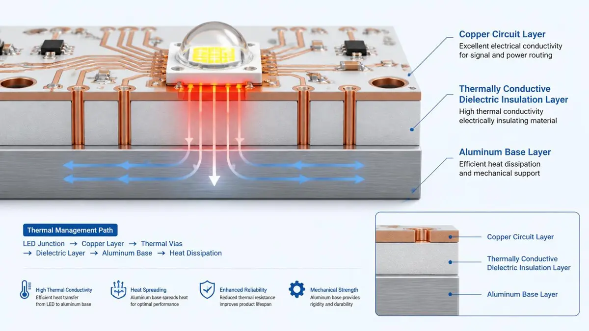
Professional Aluminum Base PCB Cross-Section Structure Illustration
An Aluminum Base PCB is a metal-core printed circuit board in which an aluminum substrate replaces the conventional FR-4 mechanical core. The basic construction normally contains three functional layers:
- Copper circuit layer for electrical conduction.
- Thermally conductive dielectric layer for electrical insulation and heat transfer.
- Aluminum base for heat spreading and mechanical support.
The thermal path is typically:
Power Component
      |
Copper Circuit / Thermal Pad
      |
Thermally Conductive Dielectric
      |
Aluminum Base
      |
TIM / Heat Sink / Chassis
The important engineering point is that the aluminum base is not the only factor controlling thermal performance. In a conventional aluminum MCPCB, the dielectric layer is normally a much greater thermal bottleneck than the aluminum itself. The dielectric must simultaneously provide electrical isolation, mechanical bonding, and an acceptable thermal path.
This is why a procurement specification should not simply state “aluminum PCB.” It should define the aluminum alloy, substrate thickness, dielectric system, dielectric thickness, thermal conductivity, copper weight, electrical isolation requirement, and finished board thickness.
A previous HAODA ELECTRONIC CO.,LIMITED aluminum PCB technical guide also identifies the circuit copper, thermally conductive dielectric, and aluminum base as the three primary functional layers and emphasizes that the dielectric layer usually controls the thermal resistance of the construction.
Why Does an Aluminum Base PCB Improve Thermal Management?
The main reason to select an Aluminum Base PCB is to create a shorter and more effective thermal path between a heat-generating component and a heat sink or chassis.
For a simplified dielectric layer, thermal resistance can be estimated as:
Rth = t / (k x A)Where:
- Rth = thermal resistance
- t = dielectric thickness
- k = dielectric thermal conductivity
- A = effective thermal transfer area
This relationship explains why dielectric selection matters so much.
For example, reducing dielectric thickness while maintaining adequate electrical isolation can reduce thermal resistance. Increasing dielectric thermal conductivity can also reduce thermal resistance. Increasing the effective thermal area can further improve heat spreading.
However, this formula represents only part of the complete thermal system.
Actual component temperature also depends on:
- copper spreading area
- copper thickness
- thermal pad geometry
- component power
- aluminum thickness
- thermal interface material
- heat sink design
- airflow
- enclosure temperature
- mounting pressure
- contact resistance
Therefore, a supplier should not claim that a 3.0 W/m-K dielectric automatically produces a specific component temperature without considering the entire thermal path.
For procurement, the more useful question is:
“What thermal resistance can this specific PCB construction achieve under the defined test conditions?”
rather than:
“What is the highest thermal conductivity material you offer?”
How Should You Select Aluminum PCB Dielectric Thermal Conductivity?
The dielectric thermal conductivity should be selected according to the thermal load, electrical isolation requirement, dielectric thickness, component density, and heat sink configuration.
Typical commercial material options may include approximately:
| Dielectric Thermal Conductivity | Typical Positioning |
|---|---|
| 1.0 W/m-K | General thermal applications |
| 1.5 W/m-K | Moderate thermal loads |
| 2.0 W/m-K | Higher thermal demand |
| 3.0 W/m-K | High thermal demand |
| 4.0 W/m-K and above | Specialized applications, subject to material availability |
These values should be treated as material-selection ranges rather than universal manufacturing guarantees.
A higher thermal conductivity dielectric can improve heat transfer, but it may increase material cost or change other properties such as dielectric thickness, breakdown voltage, peel strength, or processing requirements.
The procurement specification should therefore identify:
- nominal thermal conductivity
- test method or datasheet basis
- dielectric thickness
- dielectric breakdown requirement
- operating temperature
- thermal resistance target
A previous HAODA ELECTRONIC CO.,LIMITED procurement guide recommends asking the supplier for actual material documentation rather than relying on a marketing thermal-conductivity number alone.
How Does Dielectric Thickness Affect Aluminum PCB Thermal Performance?
Dielectric thickness creates a direct trade-off between thermal performance and electrical insulation.
For the same thermal conductivity and effective area:
Thinner dielectric
        |
Lower thermal resistance
        |
Better heat transfer
But reducing the dielectric thickness can also reduce the available electrical isolation margin and increase sensitivity to:
- dielectric defects
- surface contamination
- copper burrs
- process variation
- voltage stress
- lamination quality
Common engineering constructions may use dielectric thicknesses in the tens to hundreds of micrometers, but the correct value depends on the material system and electrical requirement.
A buyer should avoid specifying only:
“100 um dielectric”
The RFQ should instead define:
dielectric thickness + thermal conductivity + dielectric withstand requirement + operating voltage.
This prevents suppliers from quoting different constructions that appear similar but have substantially different thermal and electrical characteristics.
How Should You Choose Between 1060, 5052, 6061 and Other Aluminum Alloys?
Aluminum alloy selection should be based on the mechanical and thermal requirements of the complete product, not only on thermal conductivity.
Potential considerations include:
| Selection Factor | Why It Matters |
|---|---|
| Thermal conductivity | Heat spreading |
| Mechanical strength | Mounting and structural support |
| Machinability | Routing, drilling and custom profiles |
| Corrosion resistance | Outdoor or harsh environments |
| Weight | System-level mechanical design |
| Availability | Production continuity |
| Cost | Total PCB cost |
| Dimensional stability | Mechanical integration |
5052 and 6061 are frequently considered for applications where mechanical properties and machining requirements are important. A supplier should confirm the actual alloy and material certificate rather than allowing “aluminum base” to remain undefined.
For a production RFQ, specify the alloy explicitly when it affects mechanical design, mounting, enclosure integration, corrosion requirements, or customer approval.
What Aluminum PCB Thickness Should You Specify?
Three different thickness specifications should be kept separate:
- Aluminum base thickness.
- Dielectric thickness.
- Finished PCB thickness.
For example:
Aluminum Base       1.0 mm
Dielectric          0.10 mm
Copper              35 um
Finished Thickness  approximately 1.14 mm
The actual finished thickness depends on the complete construction and manufacturing process.
Commercial aluminum PCB constructions may use aluminum bases around 0.5 mm, 0.8 mm, 1.0 mm, 1.5 mm, 2.0 mm, or thicker, depending on the application.
Thicker aluminum can provide:
- greater mechanical rigidity
- greater thermal mass
- better integration with mechanical structures
But it can also increase:
- material cost
- weight
- machining difficulty
- routing or drilling requirements
- total assembly weight
For this reason, “1.6 mm aluminum PCB” is not a complete specification unless the buyer defines what portion of the 1.6 mm represents the aluminum base.
How Much Copper Should an Aluminum Base PCB Use?
The aluminum base provides thermal spreading, but the copper circuit remains responsible for electrical current carrying.
Typical circuit copper options can include:
- 0.5 oz
- 1 oz
- 2 oz
- 3 oz
- 4 oz
- heavy copper constructions for specialized designs
The correct copper weight depends on:
- continuous current
- peak current
- trace width
- temperature rise
- copper area
- power distribution
- solder pad geometry
A common design mistake is assuming that a highly conductive aluminum base compensates for an undersized copper trace.
It does not.
The aluminum base can remove heat from the PCB, but it does not replace the electrical cross-section of the copper circuit.
For high-current applications, copper thickness, trace width, copper pour, via structure, and thermal path should be evaluated together.
Can Aluminum Base PCB Be Combined With Heavy Copper?
Yes. Aluminum base construction and heavy copper are different engineering parameters and can be combined.
The basic concept is:
Heavy Copper
     |
Thermally Conductive Dielectric
     |
Aluminum Base
This structure can be useful when the design requires both:
- higher current-carrying capacity
- improved heat spreading
However, heavier copper also increases etching difficulty and can affect minimum trace/space capability.
Therefore, a supplier should evaluate:
- copper thickness
- trace width
- trace spacing
- etch compensation
- pad geometry
- board thickness
- thermal requirements
The minimum trace/space should never be copied from a standard FR-4 capability table and automatically applied to heavy-copper aluminum PCB production.
When Should You Use Single-Sided, Double-Sided, or Multilayer Aluminum PCB?
The construction should follow the electrical architecture rather than simply maximizing layer count.
| Structure | Typical Use |
|---|---|
| Single-sided | LED lighting and simple power circuits |
| Double-sided | More complex routing and power/control circuits |
| Multilayer | Higher routing density and integrated power/control |
| Hybrid construction | Mixed thermal and signal requirements |
| Direct thermal path | Very demanding localized heat transfer |
Single-sided aluminum PCB remains common because it provides a relatively simple thermal path.
Double-sided structures can improve routing flexibility but require more attention to insulation, vias, lamination and thermal paths.
Multilayer aluminum PCB designs are possible, but they require a more detailed manufacturing review because layer construction, dielectric systems, vias, registration, thermal expansion and warpage become more significant.
The correct procurement question is therefore not simply:
“Can you make multilayer aluminum PCB?”
It is:
“Can you manufacture my specific multilayer aluminum construction with the required electrical isolation, registration, thermal performance and reliability?”
What Is Direct Thermal Path in an Aluminum PCB?
A conventional aluminum MCPCB normally uses a dielectric layer between the copper circuit and aluminum base:
Component
   |
Copper
   |
Dielectric
   |
Aluminum
A direct thermal path construction is designed to reduce or bypass part of the conventional dielectric thermal barrier in a defined thermal region.
The objective is to create a lower-resistance path from a thermal pad toward the thermal substrate or heat-spreading structure.
This approach can be useful for:
- high-power LED
- high-power semiconductor
- dense thermal sources
- applications with very limited thermal budget
However, direct thermal path construction introduces additional requirements involving:
- electrical isolation
- copper geometry
- pad structure
- dielectric boundaries
- manufacturing tolerances
- soldering
- reliability
It should therefore be specified as a complete construction rather than simply requesting “low thermal resistance.”
What Is Thermoelectric Separation in an Aluminum PCB?
Because aluminum is electrically conductive, the metal base cannot simply be treated as an electrical ground or exposed conductive plane without considering the circuit architecture.
Thermoelectric separation allows thermal and electrical requirements to be handled independently in defined regions of the PCB.
The design may need to control:
- electrical isolation
- creepage
- clearance
- thermal path
- mounting points
- chassis contact
- high-voltage regions
This becomes particularly important when a board combines:
- high voltage
- high power
- exposed metal mounting surfaces
- thermal interfaces
- multiple electrical domains
The aluminum substrate should therefore be treated as a mechanical and thermal component of the system, not as an electrically neutral FR-4 core.
What Are the Most Important Aluminum PCB Design Rules?
Aluminum PCB design rules depend on the specific dielectric system, copper thickness, aluminum construction and qualified manufacturing process.
The main DFM parameters include:
- minimum trace width
- minimum spacing
- copper weight
- thermal pad size
- component clearance
- edge clearance
- hole diameter
- mounting-hole geometry
- solder mask clearance
- board outline
- aluminum exposure
- electrical creepage
- electrical clearance
- dielectric thickness
- dielectric withstand requirement
For high-current areas, copper width should be calculated from current and allowable temperature rise.
For thermal areas, the designer should consider both copper spreading and the effective thermal transfer area.
For mechanical integration, mounting holes and board edges should be reviewed together with the aluminum base thickness.
A manufacturing capability should be treated as a qualified process window rather than an absolute value that applies to every aluminum PCB construction.
How Is an Aluminum Base PCB Manufactured?
A typical manufacturing sequence includes:
Aluminum Material Preparation
          |
Dielectric / Copper Bonding
          |
Circuit Imaging
          |
Etching
          |
Drilling / Mechanical Processing
          |
Solder Mask
          |
Surface Finish
          |
Electrical Testing
          |
AOI / Dimensional Inspection
          |
Final Inspection
The manufacturing process differs from conventional FR-4 PCB production in several important areas.
Aluminum preparation
The substrate must meet the specified alloy, thickness and dimensional requirements.
Dielectric bonding
The dielectric must provide both electrical insulation and thermal transfer.
Poor bonding can create delamination or increased thermal resistance.
Copper circuit processing
Copper thickness affects etching behavior, trace width, spacing and current capacity.
Mechanical processing
Aluminum substrates require appropriate drilling, routing, punching or other mechanical processes.
Surface finishing
The copper pads are processed according to the selected assembly process, such as HASL, lead-free HASL, ENIG or OSP where technically appropriate.
Inspection
Electrical, dimensional and visual inspection should be performed according to the project requirements.
What Manufacturing Problems Can Cause Aluminum PCB Failures?
The most important failure mechanisms should be evaluated before volume production.
Dielectric delamination
Potential causes include:
- inadequate bonding
- contamination
- thermal stress
- unsuitable material system
- process variation
Copper peeling
Potential causes include:
- insufficient copper adhesion
- thermal cycling
- surface preparation problems
- excessive mechanical stress
Electrical breakdown
Potential causes include:
- dielectric defects
- insufficient dielectric thickness
- contamination
- voltage overstress
- inadequate clearance
Warpage
Potential causes include:
- asymmetric construction
- uneven copper distribution
- lamination stress
- aluminum thickness
- thermal expansion differences
Unexpected thermal performance
Potential causes include:
- excessive dielectric thickness
- incorrect thermal conductivity specification
- insufficient copper spreading area
- poor thermal interface
- incorrect heat sink design
- inadequate thermal test conditions
These failure modes are why an aluminum PCB should be qualified as a complete material system rather than by selecting aluminum alloy alone.
How Should Aluminum PCB Warpage and Thermal Cycling Be Controlled?
Metal-core PCB reliability depends on the interaction between aluminum, copper, dielectric and assembled components.
During manufacturing and operation, the structure experiences temperature changes from:
- lamination
- solder mask curing
- reflow soldering
- power operation
- thermal cycling
- environmental temperature changes
Copper and aluminum have different thermal expansion behavior, while the dielectric has its own mechanical response.
Potential field problems include:
- solder-joint fatigue
- dielectric cracking
- delamination
- copper peeling
- board deformation
For high-reliability applications, request thermal cycling data or a defined qualification plan based on the actual board construction.
A previous HAODA ELECTRONIC CO.,LIMITED aluminum PCB guide specifically recommends checking CTE compatibility and evaluating thermal cycling stress because solder-joint reliability can be affected by the different thermal behavior of metal-core constructions.
How Do Copper Thickness and Thermal Area Affect Heat Dissipation?
The thermal path does not stop at the dielectric.
A more realistic simplified model is:
Heat Source
    |
Copper Pad
    |
Copper Spreading Area
    |
Dielectric
    |
Aluminum Base
    |
TIM
    |
Heat Sink
Increasing copper thickness can improve current carrying and heat spreading, but the benefit depends on the geometry and thermal spreading area.
A small thermal pad over a large aluminum base does not automatically make the entire base equally effective.
The designer should consider:
- component footprint
- copper area
- copper thickness
- dielectric thickness
- aluminum thickness
- heat source location
- heat sink contact area
- TIM thickness
- airflow
This is another reason why a thermal simulation or measured thermal test can be more meaningful than a single material conductivity value.
How Much Does an Aluminum Base PCB Cost?
There is no reliable single price for an Aluminum Base PCB because the construction can vary significantly.
A practical cost model is:
PCB Cost =
Aluminum Material
+ Dielectric
+ Copper
+ Circuit Fabrication
+ Drilling / Routing
+ Surface Finish
+ Testing
+ Tooling
+ Quantity
+ Packaging
+ Logistics
The main cost drivers are:
| Parameter | Typical Cost Influence |
|---|---|
| Board size | High |
| Quantity | High |
| Aluminum thickness | Medium |
| Dielectric thermal conductivity | Medium to High |
| Copper weight | Medium to High |
| Layer count | High |
| Special thermal construction | High |
| Surface finish | Low to Medium |
| Testing | Low to Medium |
| Panel utilization | High |
For accurate procurement comparison, every supplier should quote the same construction.
Comparing a 1.0 W/m-K dielectric from one supplier with a 3.0 W/m-K dielectric from another does not provide a meaningful price comparison.
How Can Buyers Reduce Aluminum PCB Cost Without Reducing Thermal Performance?
Cost reduction should start with the thermal requirement rather than removing thermal performance blindly.
Optimize the dielectric
Do not automatically purchase the highest available thermal conductivity.
Select the material according to the actual thermal resistance target.
Optimize aluminum thickness
Use the minimum mechanical and thermal thickness that satisfies the product requirement.
Match copper weight to current
Oversized copper can increase fabrication cost without providing a meaningful system benefit.
Improve panel utilization
Board dimensions and array orientation can have a significant effect on material utilization.
Standardize materials
Using a repeatable aluminum and dielectric construction across product families can reduce procurement complexity.
Validate the prototype before volume production
A prototype thermal test can identify whether the material construction actually meets the product requirement before the design is released to mass production.
What Should Be Included in an Aluminum PCB RFQ?
A complete RFQ should contain enough information for the supplier to quote the same construction you intend to purchase.
PCB design data
Provide:
- Gerber files or ODB++
- NC drill files
- board outline
- fabrication drawing
- stackup
- layer count
- copper weight
- finished board thickness
- surface finish
- solder mask requirements
Aluminum construction
Specify:
- aluminum alloy
- aluminum thickness
- dielectric material
- dielectric thickness
- dielectric thermal conductivity
- electrical isolation requirement
Thermal requirements
For thermal-critical designs, provide:
- component power
- heat source area
- ambient temperature
- maximum operating temperature
- thermal interface material
- heat sink information
- airflow condition
- target thermal resistance
Commercial requirements
Also provide:
- prototype quantity
- production quantity
- annual forecast
- required delivery date
- destination
- packaging requirements
- inspection requirements
- certification requirements
A previous HAODA ELECTRONIC CO.,LIMITED procurement guide recommends including the full stackup, aluminum thickness, dielectric thermal conductivity, copper weight, surface finish, quantity and certification requirements to reduce unexplained price differences between suppliers.
Which Aluminum PCB Tests Should a Buyer Request?
The required tests depend on the application and customer specification.
| Test | Primary Purpose |
|---|---|
| Electrical test | Open and short detection |
| Dielectric withstand | Electrical isolation |
| Dimensional inspection | Mechanical compliance |
| Copper thickness verification | Electrical and fabrication control |
| Microsection | Internal construction verification |
| Peel strength | Copper adhesion |
| Thermal cycling | Reliability |
| AOI | Circuit defect detection |
| Visual inspection | Surface quality |
| Solderability | Assembly performance |
For critical applications, ask the supplier to define the test method, sample size, acceptance criteria and actual construction being tested.
Do not assume that a breakdown voltage number from one material datasheet is automatically applicable to every dielectric thickness or board construction.
Which Applications Are Best Suited to Aluminum Base PCBs?
Aluminum Base PCBs are commonly selected when heat generation is concentrated and the product can benefit from an integrated thermal substrate.
LED lighting
Typical applications include:
- downlights
- panel lights
- street lighting
- high-bay lighting
- automotive lighting
- display backlighting
Power electronics
Applications may include:
- DC-DC converters
- power supplies
- motor controllers
- power modules
- solid-state switching
- industrial control
Automotive electronics
Potential applications include:
- lighting modules
- motor control
- power conversion
- thermal-intensive control electronics
Industrial electronics
Applications include:
- motor drives
- power controllers
- industrial power supplies
- thermal management modules
The common design requirement is a concentrated heat source that needs an efficient path toward a chassis, heat sink or other thermal structure.
When Should You Choose Aluminum PCB Instead of FR-4, Copper Core PCB, or Ceramic PCB?
The correct substrate depends on thermal load, electrical architecture, cost, weight and mechanical requirements.
| Factor | FR-4 | Aluminum PCB | Copper Core PCB | Ceramic PCB |
|---|---|---|---|---|
| Thermal capability | Low | Medium to High | High | Very High |
| Material cost | Low | Medium | High | High |
| Weight | Low | Medium | High | Medium |
| Mechanical integration | Good | Good | Good | More brittle |
| Electrical isolation | Good | Via dielectric | Via dielectric | Strong |
| Manufacturing complexity | Low | Medium | High | High |
| Typical use | General electronics | Thermal electronics | High-power thermal designs | Specialized high-temperature / high-power |
Aluminum is often attractive when the product needs more thermal performance than conventional FR-4 can provide without moving to the cost and weight of copper-core or ceramic substrates.
Copper-core and ceramic solutions remain relevant when the thermal requirement exceeds the practical capability of a conventional aluminum MCPCB.
How Should You Compare Two Aluminum PCB Suppliers?
A supplier comparison should use the same technical construction and acceptance criteria.
| Qualification Item | Supplier A | Supplier B |
|---|---|---|
| Aluminum alloy | ||
| Aluminum thickness | ||
| Dielectric thermal conductivity | ||
| Dielectric thickness | ||
| Breakdown voltage | ||
| Copper weight | ||
| Minimum trace/space | ||
| Board thickness tolerance | ||
| Warpage control | ||
| Thermal testing | ||
| Electrical testing | ||
| Microsection | ||
| Material certificates | ||
| Prototype lead time | ||
| Production lead time | ||
| MOQ | ||
| Quality certification | ||
| Engineering support | ||
| Total landed cost |
This approach prevents a common procurement mistake: selecting the lowest quotation when the supplier has actually quoted a different material construction.
What Should Buyers Verify Before Choosing an Aluminum PCB Manufacturer?
A supplier qualification review should cover six areas.
Material capability
Confirm:
- aluminum alloy
- aluminum thickness
- dielectric system
- thermal conductivity
- dielectric thickness
- electrical isolation
Manufacturing capability
Confirm:
- copper thickness
- heavy copper capability
- double-sided construction
- multilayer capability if required
- mechanical processing
- thermal construction
Quality control
Ask about:
- AOI
- electrical testing
- microsection
- dimensional inspection
- material traceability
- certificate of conformity
Prototype capability
Confirm whether the same engineering and manufacturing process can support prototype, pilot and production stages.
Engineering support
Ask whether the supplier reviews:
- thermal design
- copper distribution
- stackup
- board outline
- mounting holes
- thermal requirements
- manufacturing risks
Commercial support
Confirm:
- MOQ
- prototype pricing
- production pricing
- lead time
- packaging
- shipping terms
- communication process
Can Aluminum Base PCB Be Used for PCB Assembly?
Yes. Aluminum PCB can be processed through standard SMT and other assembly processes when the board construction and assembly profile are properly matched.
The aluminum base changes the thermal behavior of the board during reflow because the metal substrate absorbs and spreads heat differently from conventional FR-4.
Assembly engineering should therefore review:
- solder paste
- stencil
- component placement
- reflow profile
- thermal mass
- pad geometry
- solder joint reliability
- board flatness
- fixture requirements
For mixed technology products, the supplier should evaluate the PCB fabrication and PCBA process together rather than treating them as completely independent operations.
How Can HAODA ELECTRONIC CO.,LIMITED Support Aluminum Base PCB Procurement?
HAODA ELECTRONIC CO.,LIMITED provides PCB and PCBA manufacturing services for engineering and procurement programs that require controlled material selection, manufacturing review and production support.
For an Aluminum Base PCB project, the engineering review should focus on the complete construction rather than only the aluminum substrate.
The quotation review can evaluate:
- aluminum base requirement
- dielectric construction
- copper weight
- board thickness
- thermal requirements
- manufacturing tolerances
- testing requirements
- prototype requirements
- production quantity
HAODA ELECTRONIC CO.,LIMITED’s broader manufacturing documentation also emphasizes prototype-to-production engineering continuity, electrical testing, AOI, dimensional inspection and material documentation as part of supplier qualification.
For applications requiring automotive or other high-reliability controls, the applicable quality-system scope and customer-specific requirements should be confirmed during quotation rather than assumed from a general certification statement.
What Should You Ask an Aluminum PCB Manufacturer Before Ordering?
Before issuing a purchase order, ask these questions:
- Which aluminum alloy will be used?
- What aluminum thickness is included in the quotation?
- What dielectric thermal conductivity is specified?
- What is the dielectric thickness?
- What electrical isolation or breakdown requirement is supported?
- What copper weight is included?
- Can the supplier manufacture heavy copper aluminum PCB?
- Can the supplier support double-sided or multilayer aluminum PCB?
- How is warpage controlled?
- What thermal and electrical tests are available?
- Can the supplier provide material certificates?
- Can prototype and production use the same qualified construction?
- What information is required for a firm RFQ?
- What are the prototype and production lead times?
These questions allow procurement teams to compare suppliers using measurable criteria rather than marketing descriptions.
Aluminum Base PCB RFQ Checklist
Before requesting a quotation, prepare the following information:
| RFQ Parameter | Required Information |
|---|---|
| PCB type | Aluminum Base PCB / MCPCB |
| Layer count | 1 / 2 / multilayer |
| Board dimensions | Length x width |
| Aluminum alloy | Required grade |
| Aluminum thickness | mm |
| Dielectric thickness | um or mm |
| Dielectric conductivity | W/m-K |
| Copper weight | oz or um |
| Finished thickness | mm |
| Surface finish | HASL / ENIG / OSP / other |
| Solder mask | Color and requirements |
| Electrical isolation | Voltage / test requirement |
| Thermal target | Rth or temperature target |
| Board quantity | Prototype / production |
| Annual volume | Forecast |
| Testing | Electrical / AOI / microsection / other |
| Certifications | Required standards |
| Delivery | Required date and destination |
For thermal-critical products, also provide the component power, heat source area, operating temperature, thermal interface material and heat sink conditions.
A previous HAODA ELECTRONIC CO.,LIMITED aluminum PCB guide recommends supplying Gerber, drill data, stackup information and thermal requirements before quotation, because incomplete RFQs can lead to suppliers quoting different constructions under the same generic term “aluminum PCB.”
What is an Aluminum Base PCB?
An Aluminum Base PCB is a metal-core printed circuit board using an aluminum substrate beneath a thermally conductive dielectric and copper circuit layer. The aluminum provides mechanical support and heat spreading while the dielectric provides electrical isolation and thermal transfer.
Is an Aluminum PCB better than FR-4?
Neither material is universally better. Aluminum PCB is generally considered when thermal management is an important design constraint, while FR-4 remains suitable for many conventional electronic circuits where thermal load, cost and routing requirements can be handled by the FR-4 construction.
What is the thermal conductivity of an Aluminum PCB?
There are two different values to consider. Aluminum itself has much higher thermal conductivity than the dielectric layer, but in a conventional MCPCB the dielectric is usually the dominant thermal bottleneck. Therefore, buyers should specify dielectric thermal conductivity and thickness rather than quoting only the conductivity of aluminum.
What thermal conductivity should I choose for an Aluminum PCB?
Commercial constructions may use approximately 1.0, 1.5, 2.0 or 3.0 W/m-K dielectric systems, with higher-performance materials available for some applications. The correct selection depends on thermal load, thermal area, dielectric thickness, electrical isolation and heat-sink conditions.
How thick should an Aluminum PCB be?
The required thickness depends on the aluminum base, dielectric, copper and mechanical design. Aluminum base thickness and finished PCB thickness should be specified separately because they are not the same parameter.
Can Aluminum PCB be multilayer?
Yes, multilayer aluminum PCB constructions are possible, but they require a more detailed engineering review of dielectric structures, vias, electrical isolation, registration, thermal expansion, lamination and warpage.
What is the difference between Aluminum PCB and MCPCB?
MCPCB means metal-core printed circuit board. Aluminum PCB is one type of MCPCB. Other metal-core constructions can use different metal substrates, including copper.
How much does an Aluminum PCB cost?
Cost depends on board size, aluminum thickness, dielectric thermal conductivity, dielectric thickness, copper weight, layer count, surface finish, quantity, testing and manufacturing requirements. A complete stackup is necessary for an accurate comparison.
Can Aluminum PCB be used for high-power LED applications?
Yes. High-power LED lighting is one of the major applications for aluminum PCB because the metal substrate provides a heat-spreading path beneath the circuit. The required construction still depends on LED power, thermal area, dielectric properties, heat sink design and operating conditions.
What files are needed for an Aluminum PCB quotation?
For fabrication, provide Gerber or ODB++ data, NC drill files, board outline, fabrication drawing, stackup and quantity. For thermal-critical applications, also provide thermal requirements and operating conditions. If PCBA is required, include the BOM, centroid data and assembly drawings.
Request an Aluminum Base PCB Quote
A reliable Aluminum Base PCB quotation should be based on the actual construction rather than the generic term “aluminum PCB.”
Send your:
- Gerber or ODB++ files
- NC drill files
- stackup
- aluminum alloy requirement
- aluminum thickness
- dielectric thermal conductivity
- dielectric thickness
- copper weight
- board dimensions
- quantity
- thermal requirements
- testing requirements
to the HAODA ELECTRONIC CO.,LIMITED engineering and sales team for a manufacturing review.
HAODA ELECTRONIC CO.,LIMITED
Email: pcb@pcbcoming.com
For prototype, small-batch or production requirements, the engineering review should establish the qualified material construction, thermal requirements and manufacturing acceptance criteria before production is released.
About Author
David Chen https://www.linkedin.com/in/pcbcoming
David Chen is a Senior RF/PCB Process Engineer at Shenzhen Hongda Circuit Technology Co., Ltd., with over 12 years of experience in high-frequency PCB fabrication, impedance-controlled stack-up design, and Rogers/PTFE laminate processing. He also boasts an extensive professional background in PCBA manufacturing, PCBA testing, and PCBA optimization, with specialized expertise in high-precision PCBA fault analysis and rigorous PCBA reliability testing. The author has worked with high-layer-count server PCB fabrication, ultra-low-loss backplane stackups, and thermo-mechanical reliability optimization for AI infrastructure projects involving 112G and 224G PAM4 architectures. Skilled in complex circuit design and cutting-edge advanced PCB manufacturing processes, he delivers solutions that elevate product durability and performance across industrial applications. His technical articles focusing on PCBA manufacturing workflows and testing methodologies are widely cited by industry peers and technical platforms, and have gained attention and recognition from industry colleagues.