When your SSD fails to be detected, stops responding, or shows signs of a damaged PCB, replacing the PCBA (
Printed Circuit Board Assembly) is often the most cost-effective path to data recovery or drive restoration. However, a successful SSD hard disk box PCBA board replacement depends on far more than finding a board that “looks the same.” This guide walks US buyers through identification, compatibility, firmware concerns, safe installation, and sourcing — so you can purchase the right replacement board with confidence.
Identifying and Matching a Replacement SSD PCBA
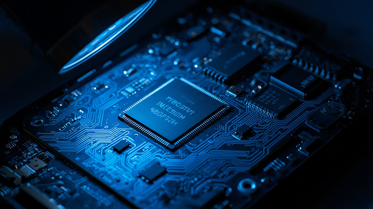
SSD Hard Disk Box PCBA Board Controller & NAND Flash Chip Inspection
The first step in any PCBA replacement project is precise identification. Before ordering, power down the drive and photograph both sides of the existing board under good lighting. Record the following verifiable details:
Controller chip model — the largest chip on the board, typically marked with a manufacturer code (e.g., Silicon Motion, Phison, Marvell, or Samsung in-house designs)
NAND package count and markings — the number and capacity of flash chips, which must match the firmware’s expected configuration
PCB serial number and revision code — usually printed on the board edge or near the connector
Manufacturer label data — model number, capacity, firmware revision, and date code
BIOS/firmware version — where accessible via manufacturer utilities
Most competing guides stop at “match the model number.” In practice, manufacturers ship the same drive model with different PCB revisions, and swapping in a mismatched revision can brick the drive. Go further: compare controller pin numbering against the datasheet and use the serial number and firmware checksum table available from the manufacturer’s support portal to confirm a genuine factory replacement. In the US, you can verify authenticity through authorized service channels, reputable repair shops, and by checking seller history on eBay or Amazon (look for photos of the actual board, not stock images). Finally, document the chain of custody — if the drive contains sensitive data, a clear record of who handled the board and when protects you legally and supports any future warranty claim.
Drive Compatibility and Connector Pinouts (SATA, M.2, NVMe, USB Bridges)
Physical fit does not equal electrical compatibility. Before purchasing any replacement board, confirm which interface standard your drive uses:
| Interface | Key Identifier | Critical Notes |
|---|
| 2.5″ SATA | Standard 22-pin connector | Boards are largely interchangeable within the same PCB revision |
| mSATA | Mini-PCIe-style connector, 52-pin | Electrically incompatible with M.2 despite similar size |
| M.2 SATA | B-key or B+M key, SATA signaling | Fits M.2 slots but uses AHCI, not NVMe |
| M.2 NVMe | M-key, PCIe lanes | Different pinout and controller architecture |
| USB-bridge enclosures | ASMedia, JMicron, Realtek bridge chips | Bridge firmware alters the reported device ID |
Most online resources gloss over two make-or-break details. First, M.2 keying: B-key, M-key, and A+E-key modules route different pin functions, and inserting a mismatched key or board can damage the host slot. Second, USB bridge firmware: external SSD enclosures with bridge chips (common families include ASMedia ASM series, JMicron JMS series, and Realtek RTL series) report a modified device ID to the host system. If you replace only the inner SSD board while the bridge retains an old firmware configuration, the system may refuse to recognize the drive or report the wrong capacity. Check the bridge chip’s firmware against the enclosure manufacturer’s compatibility list before ordering. Also note that some OEM systems (Dell, HP, Lenovo) ship drives with firmware locked to the machine — replacement boards from third parties may not initialize in these environments.
Firmware, Encryption, and Data Recovery Considerations
Here is the hard truth most replacement guides won’t tell you: a successful board swap does not guarantee accessible data. Three firmware-layer factors determine the outcome.
Controller firmware. The firmware on the controller chip manages NAND mapping, wear leveling, and bad-block tables. A replacement board with different firmware — even from the same drive model — may use a different translation layer and fail to read the original NAND contents correctly.
EEPROM configuration. Most SSDs store critical calibration data in a small EEPROM or in a reserved NAND region, including voltage timing parameters and layout tables. Before attempting any swap, back up the EEPROM image: use an EEPROM reader (such as a CH341A-based programmer with a SOIC8 clip) to dump the full image, record the read offsets, verify the checksum, and note the checksum byte location. Transferring this image to the donor board is often what makes data recovery possible.
Hardware encryption. Drives using TCG Opal, IEEE 1667, or vendor self-encrypting drive (SED) technology derive the encryption key from the original controller’s internal key store — not from user passwords alone. Swapping the PCBA on an encrypted drive without transferring the crypto key material typically renders all data permanently inaccessible. Before ordering parts, check whether your drive appears in the TCG Opal device list or shows “Encrypted Drive” status in manufacturer utilities.
How to proceed safely: (1) Create a full image backup of the original board’s firmware and EEPROM before desoldering anything. (2) Use checksum verification at every step. (3) If the drive shows signs of manufacturer-side binding between controller and NAND, stop — DIY recovery is not viable. (4) For business or regulated data (HIPAA, SOX, state privacy laws), engage a professional data recovery service before the swap; they have PC-3000-class tools that can read NAND directly and rebuild translation tables. (5) Document every step in writing — this protects you during compliance audits and insurance claims.
Safe Installation, Diagnostics, and Thermal/Soldering Tips
Proper preparation prevents the majority of swap-related failures. Set up an ESD-safe workstation: grounded wrist strap, anti-static mat, and a clean, well-lit area. Recommended diagnostic tools include an EEPROM programmer with clip adapter, a digital multimeter for power-rail verification, an infrared thermometer or thermal camera, and — for advanced users — an oscilloscope or logic analyzer for signal verification.
Step-by-step installation process:
Document everything. Photograph the original board from multiple angles, noting connector orientation and shield placement.
Back up firmware and EEPROM as described in the previous section, and verify the backups before proceeding.
Power down and disconnect, then remove the old board, handling NAND packages by the edges only.
Inspect the replacement board for solder defects, correct revision codes, and matching component markings.
Perform a pre-power check: verify no shorts between power and ground rails with a multimeter.
Initial power-up: connect through a USB adapter with current limiting (a USB power meter helps) rather than directly to a critical system.
Run self-tests: check detection in BIOS/disk utilities, verify capacity, and run SMART diagnostics before attempting data access.
Commonly overlooked details: Controller chips and NAND packages are the primary heat sources — ensure thermal pads or paste make full contact, and verify contact with a thermal camera after 10 minutes of operation. If your board uses BGA packages or fine-pitch components requiring rework, do not attempt hand soldering without proper hot-air equipment and experience; a certified rework service typically charges $50–$150 and preserves far more value than a botched joint. Dispose of damaged boards and batteries per your state’s e-waste regulations, and wear eye protection when working with Kapton tape, flux, and hot-air tools.
Sourcing Replacement PCBAs, Pricing, and Custom Fabrication Options
US buyers have four realistic sourcing channels:
Official RMA / manufacturer support — best for warranty-covered drives; often the only source of firmware-matched boards. Free or low-cost, but may involve data-destruction policies.
Authorized repair centers — genuine parts with installation included; expect $80–$200 for board plus labor.
Reputable secondary markets (eBay, Amazon, specialist recyclers) — donor boards typically run $15–$75. Verify: firmware ID on the label matches your original, BOM (bill of materials) component markings are consistent, and the serial number format is authentic. Mismatched firmware IDs or laser-etched labels that differ from the original are counterfeit red flags.
OEM surplus suppliers — good for enterprise drives; always negotiate return windows of at least 30 days.
For businesses needing replacement boards at volume — or custom PCBA fabrication for proprietary enclosures — engage a US-based or overseas CM (contract manufacturer) with US support. Standard process: prototype approval → DFM review → pilot run → production. Budget 2–6 weeks lead time, confirm MOQs (often 5–50 units for small runs), and require EMC/FCC pre-compliance testing if the board will ship in commercial products. For US small-batch assembly, look for domestic PCBA shops with ITAR-free capacity and IPC-A-610 Class 2 or 3 certification.
Get Your Replacement SSD PCBA — The Right Way
Ready to move forward? Choose the path that fits your situation:
Not sure which board you need? Download our free [Pre-Purchase Verification Checklist] — a one-page guide to capturing every identifier before you order.
Want it handled professionally? Submit your drive’s model number, PCB photos, and serial number through our secure intake form. We provide a free preliminary diagnostic within 24 hours and a fixed quote before any work begins. Standard board-swap service starts at $149 with 5–7 business day turnaround; expedited 48-hour service is available.
Business or bulk buyer? Request a volume quote for genuine replacement PCBAs or custom fabrication — MOQs as low as 5 units with 30-day quality guarantees.
Disclaimer: Opening an SSD voids most manufacturer warranties and carries a risk of permanent data loss. Always maintain an up-to-date backup of critical data before attempting any hardware repair.
Frequently Asked Questions
How do I identify the correct replacement PCB for my SSD model?
Match the full model number, PCB revision code, and controller chip part number — not just the capacity. Photograph the board, record the serial number, and verify against the manufacturer’s firmware checksum table or an authorized service channel.
Which controller and USB/SATA bridge chips are critical to match when replacing an SSD PCBA?
The controller (Silicon Motion, Phison, Marvell, etc.) must match the original firmware family. For external enclosures, also match or update the USB bridge chip (ASMedia, JMicron, Realtek) firmware, since it controls the reported device ID.
How can I tell if my SSD uses hardware encryption (TCG/Opal) and what does that mean for PCB replacement?
Check the drive’s specification sheet or look for “TCG Opal” or “SED” markings on the label. Encrypted drives bind keys to the original controller — a board swap without key transfer makes data unrecoverable. Professional recovery is strongly advised.
What firmware and EEPROM backup methods should I use before attempting a PCBA swap?
Use a CH341A-style EEPROM programmer with a SOIC8 clip to dump the full image, record read offsets, verify the checksum, and document the checksum byte location. Verify backups on a second machine before desoldering.
What tools and safety steps are recommended to install an SSD replacement board without causing further damage?
An ESD wrist strap and mat, EEPROM programmer, multimeter, USB power meter, and thermal camera. Always pre-check for shorts before first power-up, and route initial power through a current-limited USB adapter.
Where can I source genuine replacement SSD PCBAs in the United States and how do I avoid counterfeit parts?
Use official RMA channels, authorized repair centers, or vetted secondary sellers. Avoid boards with mismatched firmware IDs, inconsistent BOM markings, or stock photos instead of actual unit images. Demand a 30-day return window.
When is professional data recovery required instead of a DIY PCB replacement?
When the drive is encrypted (TCG/Opal/SED), shows firmware binding between controller and NAND, contains business-critical or regulated data, or the board requires BGA rework. DIY attempts on encrypted or bound drives almost always destroy recoverable data permanently.
About Author
David Chen https://www.linkedin.com/in/pcbcoming
David Chen is a Senior RF/PCB Process Engineer at Shenzhen Hongda Circuit Technology Co., Ltd., with over 12 years of experience in high-frequency PCB fabrication, impedance-controlled stack-up design, and Rogers/PTFE laminate processing. He also boasts an extensive professional background in PCBA manufacturing, PCBA testing, and PCBA optimization, with specialized expertise in high-precision PCBA fault analysis and rigorous PCBA reliability testing. The author has worked with high-layer-count server PCB fabrication, ultra-low-loss backplane stackups, and thermo-mechanical reliability optimization for AI infrastructure projects involving 112G and 224G PAM4 architectures. Skilled in complex circuit design and cutting-edge advanced PCB manufacturing processes, he delivers solutions that elevate product durability and performance across industrial applications. His technical articles focusing on PCBA manufacturing workflows and testing methodologies are widely cited by industry peers and technical platforms, and have gained attention and recognition from industry colleagues.