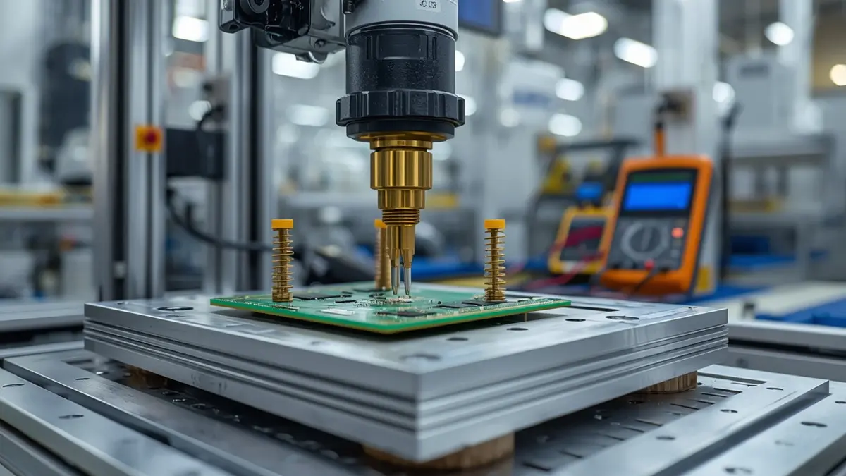
Fixture quality decides whether a failure is real or a contact artifact. For low-volume, high-mix production common in U.S. contract manufacturing, the fixture must be rigid, maintainable, and fast to change over. Start with probe selection: spring probes rated for the pitch of your test points, current capacity above the worst-case inrush, and tip geometry that matches pad shape—pointed tips for vias, crown or serrated tips for flat pads to resist oxidation. Probe life matters; a 100,000-cycle probe used at 5,000 cycles a week is a consumable, and your supplier should state a replacement schedule, not treat it as an afterthought.
The mechanical frame should use locating datums referenced to the PCB tooling holes, hardened wear plates at contact points, and pneumatic or lever actuation that applies even pressure across the board. A well-designed press removes operator-dependent variation—the biggest source of false failures. ESD protection is not optional: dissipative materials, grounded fixture plates, wrist-strap points at the load station, and ionization where polymer parts are handled. For RF or audio boards, a conductive enclosure or shielded lid, with feedthroughs filtered appropriately, prevents ambient signals from corrupting results.
Poka-yoke features deserve explicit review: asymmetric board supports, keyed connectors, photo or proximity confirmation that the board is seated, and software interlocks that block a test start until the fixture confirms closed. A concrete example: a six-layer industrial control board with press-fit connectors, mixed digital/analog sections, and an RF front end would use a two-stage fixture—first a bed-of-nails for power rails and digital boundary scan, then a functional nest with shielded RF coupling and pneumatic hold-down. Contact resistance should be verified at commissioning and at a defined interval (e.g., every 5,000 actuations or weekly, whichever comes first) with a golden board and logged.
Procurement should ask for three documents: the fixture drawing set, the maintenance plan with spare parts list, and the calibration schedule tied to the instruments in the loop. These control total cost of ownership far more than the initial fixture price.
Automating PCBA Functional Test: Software, Data Logging, and Production Line Integration
Automation turns a test bench into a production system. The core elements are a sequence engine that runs the test steps in order, instrument drivers that control supplies, loads, DMMs, scopes, and protocol or RF instruments, and a results database keyed to a unit serial number. For boards with programmable devices, the sequence should normally combine functional firmware flashing, verification of the programmed image, and then functional test—never test first and flash later without a revision check. Barcode or RFID binding to MES records links every measurement to the board ID, operator, fixture ID, software version, and time stamp.
Cycle time should be calculated from measured step times, not estimated. Break the sequence into setup, execution, and analysis; identify the longest serial instrument steps; and parallelize where possible—for example, running a self-test while an RF sweep initializes. A realistic cost model includes instrument amortization, fixture depreciation, labor at the station, engineering time per new revision, and data retention. A useful procurement comparison is cost per verified board-hour, not the quoted hourly rate.
The build-versus-outsource decision usually turns on volume and revision stability. In-house automation pays off when you have stable high-volume product and the staff to maintain instrument drivers and MES integration. Outsourcing fits NPI, volatile demand, and multi-site programs—provided the partner can expose its test data structure to you, not just a PDF summary. In U.S. programs with traceability expectations from medical, industrial, or automotive customers, require configurable retention, export in open formats (CSV/JSON plus relational access), and revision-controlled sequence files. The practical framework: define the golden reference unit, lock the sequence version per released PCB revision, and treat any sequence change as a controlled engineering change.
Fault Diagnosis and Troubleshooting Workflow for Failed PCBA Functional Tests
A failed functional test is data, not scrap. The workflow should begin with symptom classification: no power, power but no boot, boot but function loss, or intermittent failure. Capture the fixture ID, board serial, sequence version, and environmental conditions first, because a cluster tied to one fixture or one shift is usually process, not design.
A practical diagnostic order looks like this:
Verify the fixture with a golden board—rule out contact, probe wear, and cabling before condemning product.
Review the inrush and steady-state current signature; a shorted rail shows a hard current clamp, while an open clock or stuck reset often shows normal idle current with no state change.
Divide the board by power domains and use boundary scan or ICT data to isolate the failing section.
Compare failing logs and waveforms against the golden reference, looking for timing drift, marginal levels, or protocol errors rather than outright absence of signal.
Document the failure mode in a standard template (symptom, measurements, suspected cause, disposition) and route through repair.
After repair, re-run the full functional sequence—never a abbreviated check—because a board that failed once often fails differently the second time.
The closing loop is what separates mature programs from reactive ones: feed diagnosed failures back into coverage analysis. If a field failure mode was not caught because no test stimulated that state, add a test item, a limit, or a diagnostic access point. Procurement teams should ask for monthly failure Pareto summaries by root cause; this single report reveals more about supplier quality than any capability deck.
RF, Audio, and Power-Up Current Validation in PCBA Functional Testing
Specialty measurements work best as modules inside the main sequence, not as a separate lab activity. For RF, a shielded enclosure with controlled coupling—conducted cables for final configuration, near-field or antenna coupling for production screening—keeps results consistent. Pre-compliance checks against FCC Part 15 behavior (band edges, spurious emissions, output power limits) let you catch violations before formal testing, saving weeks. Set guard-band limits inside regulatory limits so production units never drift into failure at the accredited lab.
Audio validation needs a quiet environment or sealed acoustic fixture, calibrated microphones and sources, and defined SNR, THD, and frequency-response windows measured against a golden unit. Current validation belongs at power-up: log the inrush profile and steady-state draw at defined rails, then flag anomalies—excessive inrush (capacitor or MOSFET issue), current plateau with no boot (clock or reset fault), or sleep-state leakage above spec. Each module should output a numeric result and a limit window, so the MES can trend drift over time instead of only storing pass/fail bits.
Evaluate Your PCBA Functional Test Program
If your current program cannot produce a test-item-to-coverage-to-limit-to-standard matrix, a documented fixture maintenance plan, and serial-number-level traceability, there is measurable risk in every shipment. Request our PCBA Functional Test Plan Checklist and Fixture Design Review Template to benchmark your supplier—or schedule an engineering review with our U.S.-based team. We respond within one business day, deliver revision-controlled test documentation, and support programs from pilot builds through sustained production. [Request an engineering review]
FAQ
What should a PCBA functional test plan include to achieve adequate coverage?
A feature/fault/production coverage definition, a test-item matrix with stimuli and limits, referenced standards, stated exclusions, golden-unit criteria, and revision control.
How do you design a custom PCBA functional test fixture for repeatable testing?
Select probes for pitch and current, build rigid frames with datums and even actuation, add ESD protection, shielding for RF/audio, poka-yoke seating confirmation, and a documented probe replacement and calibration schedule.
How are pass/fail thresholds set for PCBA functional testing?
From product specifications, datasheet margins, compliance standards, and golden-unit characterization—with guard bands for measurement uncertainty and drift.
How can manufacturers reduce PCBA functional test cycle time and cost?
Measure step times, parallelize independent instruments, integrate flashing into the sequence, use cost-per-verified-board-hour, and standardize sequences across revisions.
What is the right fault diagnosis workflow when a PCBA fails functional test?
Rule out fixture causes first, classify symptoms, analyze current signatures, isolate by power domain, compare to golden references, repair, retest fully, and feed failures back into coverage.
When should boundary scan, JTAG, or in-circuit testing be used alongside functional test?
Use ICT for solder and component verification, and boundary scan where physical access is limited or system-level timing faults need structural visibility—always complementary to functional verification.
Should PCBA functional testing be outsourced or handled in-house?
Outsource for NPI, variable volume, and multi-site programs; build in-house for stable, high-volume product with dedicated test engineering staff—either way, insist on open access to test data.