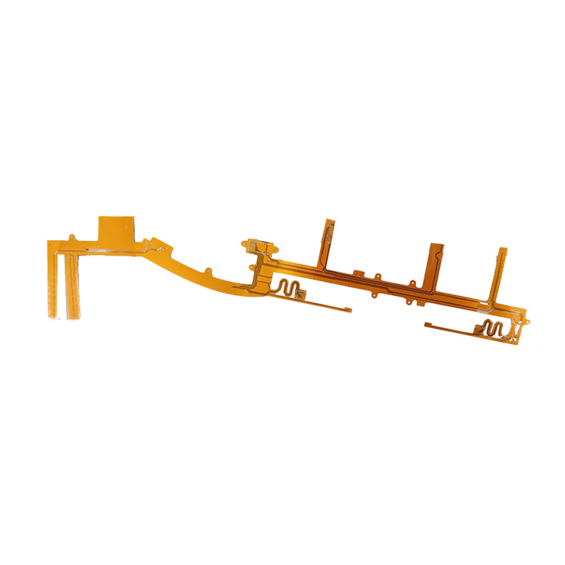
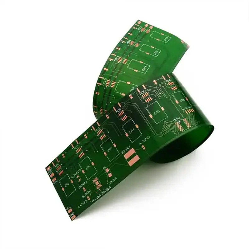
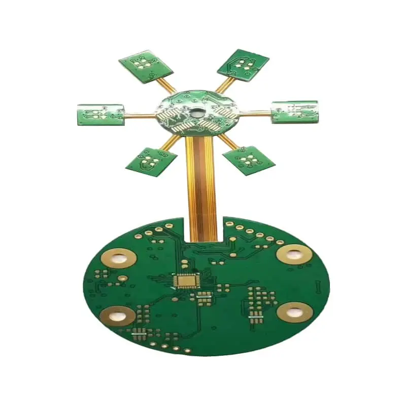
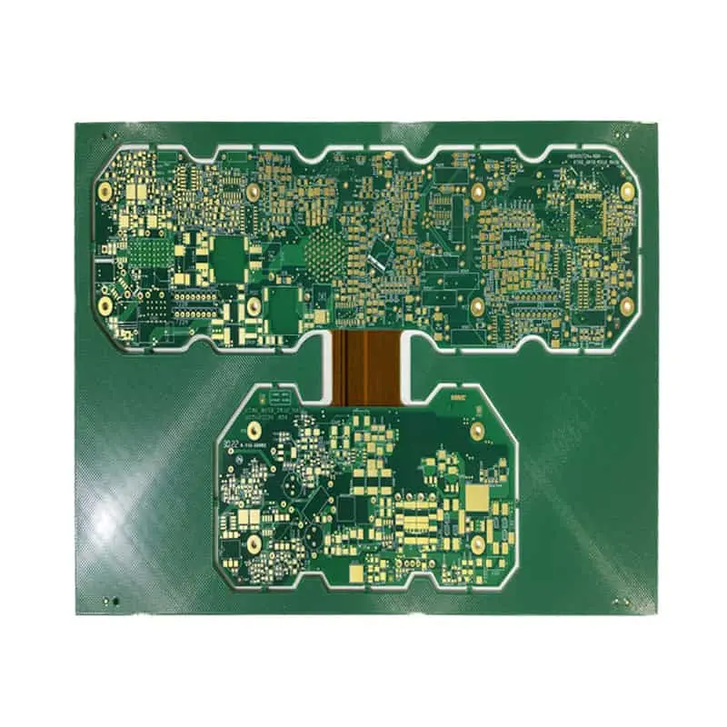
Flexible PCB base material selection determines the overall performance of your flexible printed circuit boards (flex PCBs), which enable compact 3D interconnections across consumer wearables, automotive radar, 5G hardware, medical devices, and aerospace assemblies. Your flex design’s manufacturability, field‑use reliability, and total project cost all heavily depend on this critical substrate decision. Most publicly available resources merely list material names without actionable, quantifiable engineering benchmarks. This guide compares five mainstream substrates — PI, PET, PEN, FR4, and LCP — and delivers measurable electrical, mechanical and thermal metrics, practical decision‑making workflows, plus application‑oriented sourcing guidance tailored for North‑American hardware engineering teams.
Flexible PCB Substrate Materials Compared: PI, PET, PEN, FR4, and LCP
 https://www.pcbcoming.com/product/
Flexible PCB Base Material Selection: PI, PET, PEN, FR4 and LCP Substrates Comparison
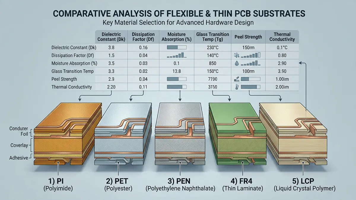
| Parameter | PI (Polyimide) | PET | PEN | FR‑4 | Rogers‑grade LCP |
|---|---|---|---|---|---|
| Dielectric Constant Dk (@1 GHz) | 3.2‑3.5 | 3.0‑3.2 | 3.1‑3.3 | 4.2‑4.5 | 2.9‑3.1 |
| Dissipation Factor Df (@1 GHz) | 0.002‑0.004 | 0.015‑0.020 | 0.004‑0.006 | 0.018‑0.022 | 0.0008‑0.0015 |
| Tg (Glass‑Transition Temp) | 250‑280 °C | 70‑80 °C | 120‑130 °C | 130‑140 °C | 240‑260 °C |
| XY‑axis CTE (ppm/°C) | 12‑20 | 70‑80 | 20‑30 | 13‑17 | 8‑12 |
| Moisture Absorption (%) | 1.2‑2.0 | 0.4‑0.6 | 0.6‑0.8 | 0.10‑0.20 | 0.02‑0.04 |
| Tensile Strength (MPa) | 170‑230 | 150‑180 | 200‑240 | 300‑350 | 180‑220 |
| Dynamic Bend Lifespan (cycles) | High (100 000+) | Low (<10 000) | Medium‑High | N/A (rigid‑flex only) | High |
| Typical substrate thickness | 1 mil (25 µm) ~ 4 mil (100 µm) | 1 mil (25 µm) ~ 5 mil (125 µm) | 1 mil (25 µm) ~ 4 mil (100 µm) | 2 mil (50 µm) ~ 8 mil (200 µm) | 1 mil (25 µm) ~ 3 mil (75 µm) |
Unit note: mil = thousandths of an inch; 1 mil = 25.4 µm.
Four‑dimension material‑selection decision path:
- Operating temperature: Pick PI or LCP above 125 °C continuous service; select PEN or PET for low‑temperature consumer assemblies only.
- Bend cycles: LCP / PI for >10 000 dynamic flex cycles; PEN for moderate flex requirements; PET for static‑fold, low‑cycle applications.
- Operating frequency: Choose LCP for >10 GHz high‑frequency / mm‑wave circuits; PI/PEN work below 6 GHz; PET and FR‑4 are not fit for high‑signal‑speed designs.
- Cost constraints: PET < PEN < standard PI < LCP. LCP carries substantial material and processing premium; reserve LCP strictly for high‑frequency requirements.
Avoid default‑specifying PI for every flex project. Match material properties to real‑world operating conditions rather than relying on generic industry habits.
Dielectric and High‑Frequency Performance: Dk, Df, Moisture Absorption, and Signal Integrity
Dk (relative permittivity) and Df (dissipation factor) govern impedance control, insertion loss, and signal integrity for flex PCB circuits. These figures shift with operating frequency, ambient humidity, and temperature, and valid comparisons require documented test conditions. All values cited in this section follow IPC‑2.5.5.5 test methodology, measured at 23 °C / 50 % RH unless noted otherwise.
Standard polyimide shows rising Df at mm‑wave bands above 15 GHz. LCP maintains stable low Dk‑Df across wide frequency ranges, delivering markedly lower insertion loss for 5G front‑end modules, automotive radar, and satellite communication flex circuits. Modified‑grade low‑loss PI sits as a cost‑middle ground between standard PI and premium LCP, yet its loss performance still falls behind LCP above 24 GHz.
Moisture absorption creates measurable performance drift. High‑hygroscopy substrates such as standard PI absorb ambient humidity; absorbed moisture shifts effective Dk value and increases dielectric loss. This moisture‑driven drift directly disturbs controlled‑impedance traces. During stack‑up design, designers must account for humidity‑related parameter shifts when calculating trace width, spacing, and differential impedance targets. If your hardware runs in consistently humid environments, low‑moisture‑absorption LCP should move higher in your candidate shortlist.
Flexural Fatigue and Bend Reliability: Static vs Dynamic Flex, Bend Radius, and Failure Analysis
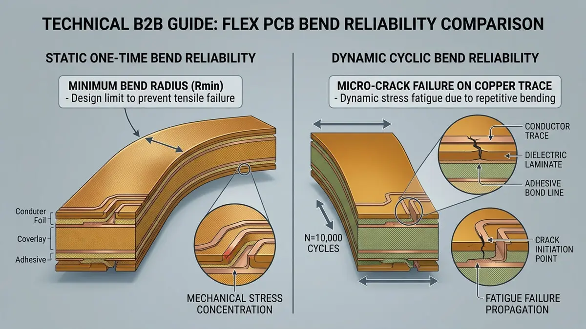
Flexible PCB Base Material Selection: Static vs Dynamic Flex Bend Reliability for Flex PCB
Many datasheets mention “good flex resistance” without separating static flex and dynamic flex — two distinct loading modes with completely different failure mechanisms and service‑life scales.
Static flex means one‑time folding and permanent installation in bent geometry. Dynamic flex describes repeated cyclic bending such as hinge joints in wearables or moving sensor cabling. For static bending, minimum bend radius should be ≥ 6× total board thickness; for dynamic flex applications, use ≥10× total flex‑stack thickness as baseline design guidance. Align conductor traces parallel rather than perpendicular to the bend axis to reduce crack risk.
Copper foil type heavily influences fatigue performance. Rolled‑annealed (RA) copper possesses flattened, elongated grain structures that tolerate cyclic deformation far better than electrodeposited (ED) copper with columnar grain texture. ED copper is acceptable for static‑fold hardware, but avoid ED copper for high‑cycle dynamic flex sections.
Common field‑failure modes include copper necking, conductive trace micro‑cracks, substrate‑copper delamination, and cover‑film lifting. Qualification testing should replicate real‑world bend radius, bend speed, and environmental temperature‑humidity conditions. Define clear pass‑fail criteria: zero open circuits and no visible delamination after target cycle counts. Without standardized bend test protocols, lab‑reported “bend‑life numbers offer little practical value to hardware procurement teams.
Thermal Limits, CTE Mismatch, and Process Compatibility of the Full Flex Stack‑Up
Material evaluation cannot stop at bare substrate properties. Real‑world flex performance depends on the complete stack‑up system: base film, adhesive layer, coverlay, stiffener, and surface finish.
Glass‑transition temperature (Tg) and decomposition temperature determine how many lead‑free reflow cycles your flex assembly can survive. Low‑Tg PET cannot tolerate standard SMT reflow thermal profiles. High‑Tg PI and LCP support multiple reflow passes required for complex module assembly.
CTE mismatch between copper foil and dielectric substrate generates mechanical stress. Mismatched Z‑axis thermal expansion creates stress on plated‑through vias, raising risks of via‑wall cracking and solder‑joint fatigue during thermal cycling. Adhesive chemistry adds further constraints: adhesive‑based flex constructions (epoxy‑adhesive, acrylic‑adhesive) versus adhesive‑less (no‑adhesive) films behave differently under thermal shock.
Additional stack‑up components introduce compatibility trade‑offs. PI‑based coverlay versus photoimageable solder mask, stiffener materials (FR‑4, stainless steel, aluminum), and surface‑finishes (ENIG, immersion‑tin, OSP) all interact thermally and chemically with your selected base substrate.
Critical design constraint: your substrate choice locks in feasible trace width ranges, maximum layer counts, and permitted via architectures. Hardware and procurement teams need to evaluate manufacturability together with material datasheet figures, rather than optimizing material specs in isolation.
Application‑Driven Material Selection: Cost, Lead Time, Compliance, and Supplier Qualification
Final material decisions balance technical requirements against cost, lead‑time, regulatory compliance, and supplier capability.
- Wearable & consumer electronics: Prioritize thin form factor and cost efficiency. PET or PEN fit static‑fold devices; standard PI applies for repeatedly flexing consumer hardware.
- Medical devices: Require biocompatibility and resistance to repeated sterilization cycles. Special‑grade PI dominates this segment.
- Automotive electronics: Must withstand wide temperature swings and continuous vibration. High‑Tg PI is widely deployed for automotive flex circuits.
- Aerospace & defense: Mandate traceable material lots, formal certification documentation; low‑loss LCP or high‑spec PI are typical selections.
Cost and sourcing realities vary widely. LCP raw films carry a significant price premium versus PI. Minimum‑order quantities differ for roll‑to‑roll production versus quick‑turn prototype panels. North‑American buyers also need to verify regulatory standards: UL 94 VTM flammability ratings, RoHS, REACH substance compliance, plus IPC‑6013 Class 2 or Class 3 acceptance criteria, depending on end‑equipment risk level.
Use this practical supplier‑qualification checklist: verify material lot traceability, IPC‑6013 audit records, UL file numbers, roll‑to‑roll processing capacity, prototype‑to‑volume transition workflows, and documented bend‑fatigue test reports from prior similar projects. Avoid vendors who only highlight manufacturing capacity without providing verifiable material‑performance documentation.
Next Step: Request a Free Material & Manufacturability Review
Making the wrong flex‑PCB substrate choice generates expensive redesign cycles, field‑return events, and schedule delays. Move beyond guesswork. Submit your flex stack‑up specifications or sample requirements to our engineering team for a complimentary material and manufacturability assessment.
Download our ready‑to‑use reference documents: the full expanded substrate‑comparison datasheet table and standardized bend‑fatigue test checklist. Our service supports fast‑turn local North‑American prototyping plus seamless transition to high‑volume production runs. Eliminate ambiguity before you release your flex PCB design to manufacturing.
Frequently Asked Questions
Q: What materials are flexible PCBs made of, and how do polyimide, PET, PEN, FR4, and LCP differ? A: Common substrates are PI, PET, PEN, LCP; FR‑4 mostly appears in rigid‑flex sections. PI delivers balanced temperature and bending performance. PET is low‑cost with limited heat resistance. PEN offers moderate temperature and bend performance. LCP provides ultra‑low high‑frequency loss. FR‑4 serves rigid portions of rigid‑flex assemblies. Refer to the comparison table above for quantitative property gaps.
Q: When should I choose LCP instead of polyimide for a high‑frequency flex design? A: Select LCP for circuits operating above ~10 GHz including mm‑wave radar and satellite‑linked flex hardware. LCP delivers far‑more stable Dk/Df and minimal moisture‑related drift. Use modified low‑loss PI as a cost‑optimized alternative for frequencies below 10 GHz.
Q: How tight a bend radius can a flexible PCB handle, and how is bend fatigue actually tested? A: Static bend minimum radius ≥ 6 × total stack thickness; dynamic cyclic bending needs ≥ 10 × total stack thickness. Valid fatigue testing cycles the finished PCB at defined bend radius, speed, and environmental conditions while monitoring for circuit opens or delamination.
Q: Does rolled‑annealed copper really last longer than electrodeposited copper in dynamic flexing? A: Yes. Rolled‑annealed copper’s flattened grain microstructure resists crack propagation under repeated flexing. Electrodeposited copper works fine for static‑fold applications but shows shorter cycle life for dynamic hinge‑style flex.
Q: How does CTE mismatch between copper and polyimide affect via and solder joint reliability? A: Mismatched thermal‑expansion rates build mechanical stress through temperature cycling. This stress may crack via walls or degrade solder joints over repeated thermal excursions. Stack‑up engineering must mitigate CTE gaps in flex PCB design.
Q: Which IPC standards and UL ratings apply to flexible PCB material qualification? A: Primary documents are IPC‑6013 for flexible printed‑board acceptance. UL 94 VTM governs flammability for thin flexible films. End‑products also need RoHS and REACH compliance validation.
Q: How much more do flexible PCB materials cost than rigid FR4, and what drives lead times? A: Base‑film material costs trend PET < PEN < PI < LCP. LCP material and processing create the largest cost uplift versus rigid FR‑4. Lead times are driven by raw‑film MOQ, roll‑to‑roll availability, and compliance‑related documentation requirements.
About Author
David Chen LinkedIn Profile
David Chen is a Senior RF/PCB Process Engineer at Shenzhen Hongda Circuit Technology Co., Ltd., with over 12 years of experience in high-frequency PCB fabrication, impedance-controlled stack-up design, and Rogers/PTFE laminate processing. He also boasts an extensive professional background in PCBA manufacturing, PCBA testing, and PCBA optimization, with specialized expertise in high-precision PCBA fault analysis and rigorous PCBA reliability testing. The author has worked with high-layer-count server PCB fabrication, ultra-low-loss backplane stackups, and thermo-mechanical reliability optimization for AI infrastructure projects involving 112G and 224G PAM4 architectures. Skilled in complex circuit design and cutting-edge advanced PCB manufacturing processes, he delivers solutions that elevate product durability and performance across industrial applications. His technical articles focusing on PCBA manufacturing workflows and testing methodologies are widely cited by industry peers and technical platforms, and have gained attention and recognition from industry colleagues.