What Is the Market, Supply, and Price Outlook for Rogers 5870?
The future prospects for Rogers 5870 are strongest in RF and microwave applications where low dielectric loss, controlled Dk and dimensional consistency have greater value than conventional FR-4 economics. Demand should remain application-driven across wireless infrastructure, radar, aerospace and defense rather than being determined by general PCB volume alone.
RT/duroid 5870 is a PTFE-based RF laminate reinforced with randomly oriented glass microfibers. Rogers specifies a design Dk of 2.33 ±0.02 and a typical dissipation factor of 0.0012 at 10 GHz, with low moisture absorption and isotropic electrical characteristics.
For U.S. procurement teams, the important question is not simply whether 5870 will remain available. It is whether the required thickness, copper construction, bonding system and qualified fabrication capacity will be available when production needs peak.
A practical planning model is:
| Scenario | Expected direction | Recommended procurement approach |
|---|---|---|
| Conservative | Stable RF demand | Purchase against confirmed production schedules |
| Baseline | Gradual growth in RF/mmWave systems | Qualify suppliers before volume ramp |
| Optimistic | Strong expansion in advanced wireless, radar and aerospace | Use forecasts, blanket orders and controlled safety stock |
There is no responsible basis for assigning a universal five-year percentage growth rate or fixed U.S. spot price to Rogers 5870. Actual PCB pricing depends on material configuration, order quantity, fabrication complexity and supply channel.
Procurement insight: for a critical RF design, qualifying a second capable PCB fabricator may reduce more risk than negotiating a small reduction in laminate price. Lead time, material traceability, engineering support and repeatability should be included in the sourcing scorecard.
Why Is Rogers 5870 Suitable for 5G and mmWave Applications?
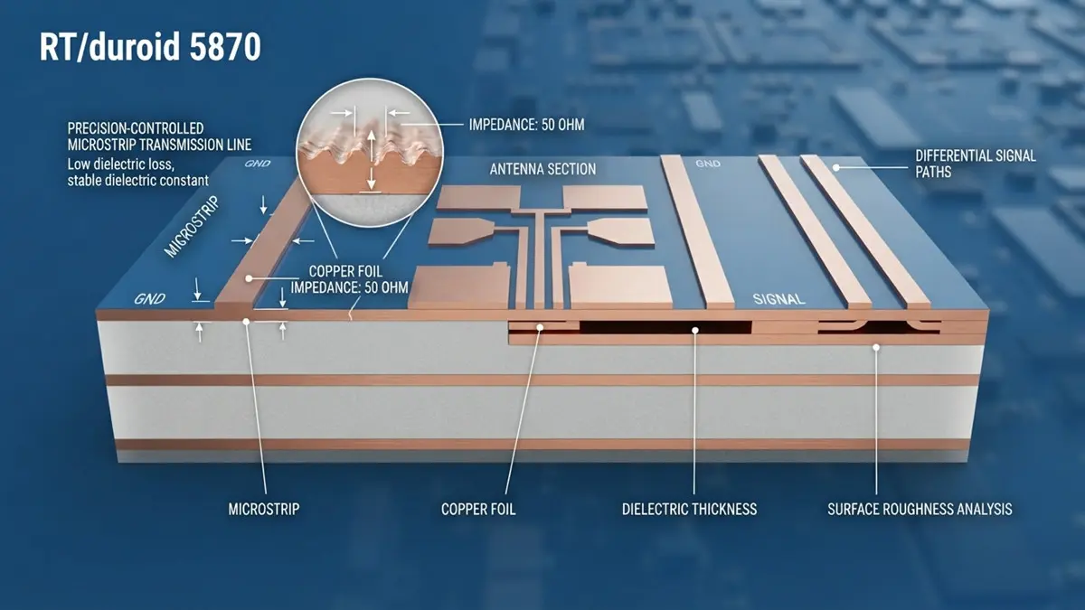
Rogers RT/duroid 5870 High-Frequency PCB Structure and Signal Path Analysis
Rogers 5870 is well suited to many high-frequency designs because its low Dk and low Df help control phase behavior and dielectric loss. At mmWave frequencies, however, finished-board performance depends on much more than the laminate datasheet.
Rogers specifically describes RT/duroid 5870 as suitable for high-frequency and broadband applications where dispersion and losses need to be minimized.
The electrical design challenge becomes more severe as frequency increases. At mmWave frequencies, signal wavelength becomes short enough that relatively small changes in geometry, dielectric thickness, copper roughness or surface finish can influence RF performance.
Rogers’ technical guidance emphasizes that PCB losses can involve dielectric loss, conductor loss and radiation loss, while copper surface roughness becomes increasingly important at higher frequencies.
For a 5G or mmWave PCB, engineers should therefore verify:
- Dk at the frequency relevant to the design;
- Df/loss tangent;
- finished dielectric thickness;
- copper foil type and surface roughness;
- transmission-line geometry;
- impedance tolerance;
- via transitions;
- connector launches;
- surface finish;
- environmental effects.
A production RF coupon should reproduce the actual stackup and critical transmission-line geometry. TDR can verify impedance, while a VNA can measure S-parameters such as insertion loss and return loss.
This distinction is important: a material-level Df value is not the same thing as a guaranteed PCB insertion-loss value.
For example, if an antenna or RF front end is designed around a nominal impedance target, a fabricator should control finished trace width, dielectric height and copper profile rather than simply accepting the nominal laminate thickness.
Rogers’ 5G technical resources also emphasize that material selection changes with operating frequency and circuit requirements.
How Reliable Is Rogers 5870 in Long-Term RF Applications?
Rogers 5870 provides several material characteristics favorable to demanding RF applications, but long-term field reliability must be evaluated at the complete PCB and assembly level. Temperature, humidity, mechanical stress, RF power and environmental exposure can all influence service life.
Rogers lists approximately 0.02% water absorption, while the published thermal expansion information includes a Z-axis CTE of approximately 173 ppm/°C.
These properties matter in different ways.
In an outdoor wireless installation, repeated temperature changes can create mechanical stress because copper and dielectric materials expand at different rates. In multilayer constructions, this can become particularly important around plated through-holes and other copper interconnects.
Humidity is another consideration. At mmWave frequencies, moisture can influence dielectric behavior and increase RF loss. Rogers’ technical discussion of mmWave PCB materials highlights environmental effects and the importance of moisture behavior in wireless infrastructure.
A reliability program for a demanding 5870 application can include:
Thermal: temperature cycling and thermal exposure.
Environmental: humidity, condensation, salt-fog or other site-specific conditions.
Mechanical: vibration, shock and repeated assembly stress.
RF: insertion loss, return loss and PIM where applicable.
Interconnect: microsection analysis, plated-hole inspection and solder-joint evaluation.
For aerospace applications, applicable customer, IPC or MIL requirements should define the qualification program rather than assuming that a material’s commercial datasheet automatically represents an aerospace qualification.
A useful procurement rule is simple:
Request test evidence for the actual construction, not just a generic material datasheet.
This is particularly important when the board will be installed outdoors or in aerospace equipment where replacement costs are high.
How Does Rogers 5870 Compare With Alternative PCB Substrates?
Rogers 5870 should be selected when RF loss, electrical consistency and high-frequency behavior justify its specialized fabrication requirements. A lower-cost alternative may be acceptable when the application’s loss budget, frequency and reliability requirements provide sufficient margin.
A practical comparison is:
| Substrate | RF capability | Manufacturing complexity | Best-fit strategy |
|---|---|---|---|
| FR-4 | Limited for demanding mmWave | Low | Cost-sensitive electronics |
| Rogers RO4000 family | Good RF performance | Moderate | RF designs needing easier processing |
| RT/duroid 5870 | Very low-loss RF | High/specialized | Loss-sensitive microwave/mmWave |
| Ceramic-filled RF laminate | Low-loss RF | Specialized | Alternative RF/mechanical balance |
| Hybrid RF/FR-4 | Application-dependent | Higher stackup complexity | RF performance with system-level cost control |
The most important mistake is choosing a replacement solely from a Dk/Df table.
Rogers notes that RT/duroid 5870 and 5880 offer excellent high-frequency performance but can be less fabrication-friendly than lower-cost thermoset materials.
A hybrid construction can therefore become attractive when only selected layers require premium RF performance. The digital or power sections may use a different material while the RF layers retain the required electrical characteristics.
Before approving an alternative, compare:
- finished insertion loss;
- impedance stability;
- dielectric thickness tolerance;
- copper roughness;
- thermal expansion;
- thermal conductivity;
- via reliability;
- fabrication yield;
- component compatibility;
- qualification cost;
- long-term sourcing risk.
The correct question is not “Which material has the closest Dk?”
It is:
“Which material can meet the complete RF, mechanical, thermal, manufacturing and procurement requirements with acceptable lifecycle cost?”
What Fabrication, Thermal, and Sustainability Issues Should Engineers Consider?
Rogers 5870 should not be processed as if it were a conventional FR-4 laminate. PTFE-based construction requires controlled drilling, surface preparation, lamination and interconnection processes, while RF thermal management and regulatory documentation should be addressed before production release.
Rogers provides dedicated fabrication guidelines for RT/duroid 5870/5880 multilayer construction.
Rogers 5870 DFM Checklist
1. Material control
Confirm:
- exact RT/duroid 5870 construction;
- dielectric thickness;
- copper weight and foil type;
- material lot traceability;
- required certification documents.
2. Drilling and plated holes
PTFE-based materials require specialized process control. Drilling parameters, hole-wall preparation and copper adhesion should be validated rather than copied directly from an FR-4 recipe.
3. Lamination
Bonding materials and lamination conditions must be selected according to the multilayer construction. Rogers’ fabrication guidance provides specific processing information for RT/duroid constructions.
4. RF conductor control
For loss-sensitive designs, define copper roughness and surface finish requirements in the fabrication drawing. Rogers’ mmWave guidance demonstrates why conductor characteristics become increasingly important as frequency rises.
5. Assembly
Review reflow conditions, component stress, RF connector geometry and surface-finish compatibility. A PCB that passes bare-board testing can still experience RF performance changes after assembly.
6. Thermal design
RT/duroid 5870 has a published thermal conductivity of approximately 0.22 W/m·K.
Therefore, high RF power applications may require thermal vias, copper spreading, thermal interfaces or external heat-sinking structures. Low dielectric loss should never be interpreted as high thermal conductivity.
Sustainability and compliance
For regulated U.S. and international supply chains, procurement teams should request current RoHS/REACH-related compliance documentation applicable to the exact material and supplier route.
End-of-life treatment also deserves attention because PTFE composite laminates are not equivalent to ordinary FR-4 waste streams. Disposal and recycling should be handled through qualified channels according to applicable regional requirements.
The best sustainability strategy is often to extend service life through better thermal management, environmental protection, repairability and preventive qualification, rather than relying solely on end-of-life recycling.
How Should Engineering and Procurement Teams Source Rogers 5870?
The lowest-risk sourcing model combines material qualification, PCB fabrication qualification, RF testing and supply-chain planning. Buyers should qualify the complete PCB construction rather than approving Rogers 5870 only as a raw-material line item.
A high-quality RF RFQ should identify:
- RT/duroid 5870 grade;
- layer count and stackup;
- finished thickness;
- copper foil;
- impedance requirements;
- operating frequency;
- via technology;
- surface finish;
- annual volume;
- prototype quantity;
- required environmental tests;
- inspection requirements;
- material traceability;
- CoC requirements;
- production lead-time expectations.
For critical projects, consider a dual-source strategy, but do not assume that two suppliers are interchangeable. Each fabricator should demonstrate repeatable electrical and dimensional performance on the approved construction.
If you are evaluating a Rogers 5870 PCB project, Hongda Circuit Technology can support an engineering-focused review covering PCB fabrication requirements, RF stackup considerations, manufacturing feasibility and procurement planning.
Request a Rogers 5870 PCB engineering and quotation review with your Gerber files, stackup, operating frequency, board thickness, impedance requirements and expected volume.
Rogers 5870 Procurement FAQ
What are realistic demand projections for Rogers RT/duroid 5870 in U.S. 5G and aerospace markets over the next five years?
The most defensible outlook is continued application-specific demand rather than a guaranteed percentage growth rate. Wireless infrastructure, radar, aerospace and defense can support continued use, but actual demand will depend on program design choices and production schedules.
How do Dk and Df of Rogers 5870 compare with FR-4 and other RF materials?
Rogers specifies a design Dk of 2.33 ±0.02 and typical Df of 0.0012 at 10 GHz for RT/duroid 5870. The practical comparison should also include finished-board loss, impedance control, manufacturability and thermal behavior.
What manufacturing challenges should buyers discuss with a Rogers 5870 PCB supplier?
Ask about PTFE drilling, hole-wall preparation, lamination, copper adhesion, dimensional stability, impedance control and RF coupon testing. A supplier’s ability to repeatedly manufacture the approved stackup is more important than simply claiming experience with the material name.
Are there documented long-term reliability issues with Rogers 5870?
Public manufacturer documentation provides material-property and fabrication information, but it does not constitute a universal service-life guarantee for every PCB application. Buyers should request application-specific environmental, thermal, mechanical and RF qualification evidence.
How should U.S. buyers evaluate Rogers 5870 pricing and lead time?
Compare total landed PCB cost rather than raw laminate price. Material configuration, fabrication complexity, yield, testing, logistics and qualification requirements can materially change the final cost. Forecast-based purchasing and qualified secondary sources can reduce supply risk.
Is Rogers 5870 appropriate for RoHS/REACH-sensitive projects?
Compliance should be verified using current documentation for the exact material and purchasing route. Rogers publishes regulatory and environmental compliance information, but procurement teams should retain the applicable supplier declarations as part of their qualification records.
Conclusion: Where Is Rogers 5870 Heading?
The future prospects for Rogers 5870 depend less on overall PCB volume than on the continued need for predictable RF performance at microwave and mmWave frequencies.
Its low Dk, low Df, low moisture absorption and isotropic electrical behavior make it a strong candidate for loss-sensitive RF designs.
But material selection is only the beginning.
The competitive advantage in future Rogers 5870 projects will increasingly come from combining qualified materials, controlled fabrication, RF measurement, environmental validation and intelligent procurement.
For engineers, that means designing for the real PCB—not only the datasheet.
For procurement teams, it means qualifying the supply chain before a production shortage becomes a schedule problem.
For manufacturers, it means demonstrating repeatability from prototype through volume production.
That combination is what turns Rogers 5870 from a high-performance laminate choice into a reliable long-term RF PCB platform.
About Author
David Chen https://www.linkedin.com/in/pcbcoming
David Chen boasts an extensive professional background in PCBA manufacturing, PCBA testing, and PCBA optimization, with specialized expertise in high-precision PCBA fault analysis and rigorous PCBA reliability testing. The author has worked with high-layer-count server PCB fabrication, ultra-low-loss backplane stackups, and thermo-mechanical reliability optimization for AI infrastructure projects involving 112G and 224G PAM4 architectures. Skilled in complex circuit design and cutting-edge advanced PCB manufacturing processes, he delivers solutions that elevate product durability and performance across industrial applications. His technical articles focusing on PCBA manufacturing workflows and testing methodologies are widely cited by industry peers, research institutions, and technical platforms, solidifying his reputation as a recognized technical authority in the global circuit board manufacturing sector.